background image

8

For Your Safety As Well As That Of Others

(Turning on the power switches)

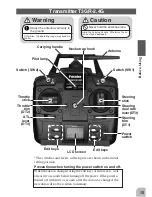
Always check the throttle stick on the transmitter to be sure it is at the neutral position.

1. Turn on the transmitter power switch.

2. Turn on the receiver or speed control power switch.

(Turning off the power switches)

Always be sure the engine is not running or the motor is stopped.

1. Turn off the receiver or speed control power switch.

2. Then turn off the transmitter power switch.

If the power switches are turned off in the opposite order the model may unexpectedly run out of control and cause
a very dangerous situation.

(Fail safe function) ---when using HRS mode

Before running (cruising), check the fail safe function.

Check Method:

Before starting the engine, check the fail safe function as follows:

1. Turn on the transmitter and receiver power switches.

2. Wait at least one minute, then turn off the transmitter power switch. (The transmitter automatically transfers the fail
safe data to the receiver every minute.)

3. Check if the fail safe function moves the servos to the preset position when reception fails.

The fail safe function is a safety feature that minimizes set damage by moving the servos to a preset position when
reception fails. However, if set to a dangerous position, it has the opposite effect.

Setting example: Throttle idle or brake position

Summary of Contents for 3GR-2.4GHZ

Page 1: ...or U S A This device trade name Futaba Corporation of America model number R603FF complies with part 15 of the FCC Rules Operation is subject to the following two conditions 1 This device may not cause harmful interference and 2 This device must accept any interference received including interference that may cause undesired operation The responsible party of this device compliance is Futaba Servi...

Page 2: ...or permission The contents of this manual are subject to change without prior notice This manual has been carefully written Please write to Futaba if you feel that any corrections or clarifications should be made Futaba is not responsible for the use of this product ...

Page 3: ...15 Installation 21 Receiver and Servo Connections 21 Installation Safety Precautions 21 Initial Set Up 23 How to link the transmitter and the receiver 23 Preparations Transmitter 24 Functions 30 End Point Adjuster 30 Steering Speed 33 Steering EXP Throttle EXP 34 A B S Function 36 Throttle Acceleration 38 Brake Mixing 40 Programmable Mixing 41 Fail Safe Battery Fail Safe HRS System Only 42 Trim 43...

Page 4: ...ch 54 Function Select Lever 55 Condition 2 Selection 56 LED Mode Selection 56 Throttle Neutral Adjuster 57 For Your Safety As Well As That Of Others Before Using Installation Initial Set Up Function Map Functions Reference Reference 58 Ratings 58 Optional Parts 59 Troubleshooting 60 Error Displays 61 When requesting repair 62 ...

Page 5: ...nd could cause death or serious injury as well as su perficial injury and physical damage Caution Indicates procedures that may not cause serious injury but could lead to physical damage Symbols Prohibited Mandatory Symbols Explanation Special attention should be paid before turning on the system while other cars are run ning or other airplanes are flying because the 2 4GHz RC system could potenti...

Page 6: ...lly to the ground Otherwise the operating range may become shorter Always perform an operating range check prior to use Problems with the radio control system as well as improper installation in a model could cause loss of control Simple range test method Have a friend hold the model or clamp it down or place it where the wheels or prop cannot come in contact with any object Walk away and check to...

Page 7: ...nd cause a very dangerous situation Fail safe function when using HRS mode Before running cruising check the fail safe function Check Method Before starting the engine check the fail safe function as follows 1 Turn on the transmitter and receiver power switches 2 Wait at least one minute then turn off the transmitter power switch The transmitter automatically transfers the fail safe data to the re...

Page 8: ...e or disconnect the NiCd battery Leaving the battery connected could create a dangerous situation if someone accidentally turns on the receiver power switch Loss of control would occur Special Charger Shock Prohibited NiCd AA size batteries Use prohibited Do not throw NiCd batteries into a fire Do not expose NiCd batteries to extreme heat Also do not disas semble or modify a NiCd battery pack Over...

Page 9: ...e humidity is high Where vibration is prevalent Where dust is prevalent Where the system would be exposed to steam and condensation Storing your R C system under adverse conditions could cause deformation and numerous problems with operations Mandatory Procedure If the system will not be used for a long period of time remove the bat teries from the transmitter and model and store in a cool dry pla...

Page 10: ...il and exhaust will pen etrate and damage the plastic Always use only genuine Futaba transmitters receivers servos FET a m p s e l e c t r o n i c s p e e d controls NiCd batteries and other op tional accessories Futaba will not be responsible for problems caused by the use of other than genuine Futaba parts Use the parts specified in the instruction manual and catalog Mandatory Procedures ...

Page 11: ...n of a model memory with different fine setups Two function groups Frequently used functions System functions Frequently used functions can be easily called from the initial screen with Select Key SEL Brake mixing for large cars BMX Brake mixing of the front and rear wheels of 1 5GP cars etc has balance adjustment functions Steering dual rate D R ST Steering angle can be adjusted with digital trim...

Page 12: ...use all the levers are digital Function select switch function FNC SW1 SW2 This function assigns a function to the two installed switches Condition 2 Selection COND2 In specific functions two rates can be set up and switched with SW1 switch simulta neously during a run NEW design considers operability and weight balance Stick Lever Head Adjustment High luminosity blue LED pilot lamp LED MD You can...

Page 13: ...only genuine Futaba transmitter receiver FET amp NiCd battery and other optional parts Futaba will not be responsible for damage caused by other than genuine Futaba parts and components Use only the genuine Futaba parts and components listed in the instruction manual and catalog Caution Always use R603FF under the following conditions Power supply 6V NiCd battery PPM HRS mode Servo 6V type Futaba ...

Page 14: ... when turning the power switch on and off When the data is changed using the edit keys or trim levers wait at least two seconds before turning off the power If the power is turned off within two seconds after the data was changed the new data will not be written to memory Edit keys Neck strap hook Carrying handle Adjust the antenna vertically to the ground Otherwise the operating range may become ...

Page 15: ...e the tone will change pitch and the lever will not move any farther Trim Operation With the digital trim feature trim adjustments have no effect on the maximum servo travel This prevents the linkages from binding when adjustments are made ATL position Steering D R rate Stick Lever Head Adjustment The length of the lever head of the steering and throttle sticks can be adjusted Adjustment 1 Unlock ...

Page 16: ...ltage is low check the batter ies for insufficient contact in the case or incorrect battery polarity Caution Always be sure you reinsert the bat teries in the correct polarity order If the batteries are loaded incorrectly the transmitter may be damaged When the transmitter will not be used for any period of time always remove the batteries If the batteries do happen to leak clean the battery case ...

Page 17: ...tter charging LED Cord to transmitter charging jack When charging the NT8F700B NiCd battery with the special charger allow about 15 hours for charging If the transmitter has not been used for some time cycle the battery by charging and discharging it two or three times Over current protection The transmitter charging circuit is equipped with an over current protection circuit If the battery is cha...

Page 18: ...e charger is not in use dis connect it from the AC outlet Do this to prevent accidents and to avoid overheat ing Caution Never plug it into an outlet of other than indicated voltage Plugging the charger into the wrong outlet may re sult in an explosion sparking or fire Do not insert and remove the charger when your hands are wet It may cause an electric shock Warning Use the special charger Set da...

Page 19: ...For the receiver servos and other connections see page 21 Connectors 3 CH3 servo CH3 2 Throttle servo CH2 1 Steering servo CH1 B C Power connector DSC connector RS232C for factory use only R603FF receiver Antenna Coaxial cable ...

Page 20: ...enna tube Antenna Coaxial cable R603FF Receiver Antenna Installation Install the R603FF receiver on the car as follows Note The operating range may become shorter depending on where the receiver and the antenna are mounted Install the antenna in the higher place as shown in the figure Keep the antenna as for away from the motor ESC and other noise sources as possible Put the antenna in the antenna...

Page 21: ...l may occur If any moisture comes in contact the receiver and servos you may experience the same result as well as damage to the system Servo Throw Operate each servo over its full stroke and be sure the linkage does not bind or is loose The continuous application of unreasonable force to a servo may cause damage and excessive battery drain Servo Installation When you install the servos always use...

Page 22: ... to see if the RF signal is transmitted When the green LED is solid ON the RF signal is transmitted Please refer the table below for LED status vs transmitter s condition LED status vs transmitter s condition Parameter check for 0 5 seconds after power on Red On Transmitting signals Green On F S is activated by the F S switch of the transmitter PPM mode Green Blink Unrecoverable failure EEPROM etc...

Page 23: ...odel number is displayed Check if this number is the model number you want to set up To change the model number use the Model Select function page 48 Modulation mode PP PPM mode HRS HRS mode Battery voltage Display when power switch is turned on 2 Modulation Mode Check The T3GR 2 4G transmitter output signal format can be changed HRS PPM Check if the modulation mode is set to the desired mode If t...

Page 24: ...alue on the screen changes After checking the trim set the trim value to the center 0 position Throttle trim DT2 check At initial set up throttle trim is assigned to digital trim DT2 Operate the DT2 lever and check if the throttle trim value on the screen changes After checking the trim set the trim value to the center 0 position Steering trim position Throttle trim position DT2 DT1 ...

Page 25: ... D R value displayed on the screen changes After checking D R set the steering dual rate to 100 Throttle ATL DT4 check At initial setting throttle ATL is assigned to digital trim DT4 Operate the DT4 lever and check if the ATL value displayed on the screen changes After checking ATL set throttle ATL to 100 Steering D R value Throttle ATL position DT3 DT4 ...

Page 26: ...n using the Reverse function Page 47 The servo installation method and linkage direction depend on the kit Therefore the servo operation direction may have to be reversed relative to transmitter operation Before in stalling the servo check the operating direction and set it us ing the Reverse function 3 Set the subtrim and adjust the servo neutral point Page 46 4 Set EPA of each channel and adjust...

Page 27: ...key to select the next set up screen Initial Screen Digital trim DT1 DT4 display The current position is displayed on the LCD screen for about two seconds when each digital trim is operated End Point Adjuster Timer Model Select Channel Reverse Subtrim Channel 3 Position ATL Function Steering D R Trim Steering Speed Steering EXP Throttle EXP ABS Function Throttle Acceleration Brake mixing Programma...

Page 28: ...de Selection Throttle Neutral Adjuster Condition 2 Selection Model Copy Function Select Lever Model Reset Function Select Switch HRS PPM Select Model Name Press SEL key to select the desired function screen Press it for one second or more to scroll to the opposite direction Press CH key to select the next set up screen ...

Page 29: ...ay be exceeded Check the linkage each time the following functions are adjusted Sub trim all channels Throttle Acceleration Brake side Brake mixing rate Program mixing slave side all channels ATL trim ATL trim allows adjustment of the brake side operation amount during operation Therefore when the operating angle is adjusted with throttle EPA ATL trim must also be taken into account Warning Make s...

Page 30: ...L key to select the desired function screen Calling the setup screen Adjustment range 0 120 each channel each direc tion Adjustment buttons Use the and keys to make ad justments Return to the initial value by pressing the and buttons simultaneously approx 1 sec Setup items ST L F U Steering left side ST R B D Steering right side TH L F U Throttle forward side TH R B D Throttle brake side 3C L F U ...

Page 31: ...When adjusting the EPA of another channel immediately after this see the adjustment method for that channel When ending adjustment return to the initial screen by pressing the SEL button 2 Throttle brake side reverse side adjustment Pull the throttle stick fully to the brake side and use the and buttons to adjust the steering angle However when using an FET amp set to 100 3 When adjusting the EPA ...

Page 32: ...ly 1 5 seconds Servo operation is delayed 操作時のスピード可変範囲 時間 約1 5 0 1秒 戻りのスピード可変範囲 約1 5 0 1秒 ス テ ィ ッ ク 操 作 TURN 方向 RETN 方向 Steering Speed SPD Quick steering operation will cause momentary understeering loss of speed or spin ning This function is effective in such cases Understeering Spin Smooth cornering Steering speed not set Steering speed set Operation This function limits the maximum speed of the...

Page 33: ...nts 1 When you want to quicken steering operation use the button to adjust the side When you want to make steering operation milder use the button to adjust the side 2 When adjusting the EXP rates of another channel immediately after this see the adjustment method for that channel When ending adjustment return to the initial screen by pressing the SEL button Setup item EXP ST Steering EXP rate EXP...

Page 34: ...e side when you want to make the rise milder 2 Brake side adjustment Select setup item EXP BK and use the button to adjust the side when you want to quicken the rise and use the button to adjust the side when you want to make the rise milder 3 When adjusting the EXP rates of another channel immediately after this see the adjustment method for that channel When ending adjustment return to the initi...

Page 35: ... intermittently This will have the same effect as pumping the brakes in a full size car The brake return amount pumping cycle and delay amount can be adjusted Without A B S With A B S Operation Display When the A B S function is activated the LED flashes Fail Safe Unit When the 3GR 2 4G system PPM mode is used with the Futaba fail safe unit FSU it will operate as described below When the FSU is co...

Page 36: ...0 position of the brake operation amount 100 Return to the neutral position 3 Cycle speed adjustment Select setup item ABS CY and use the and buttons to adjust the speed The lower the set value the faster the cycle speed 4 Delay amount setup Select setup item ABS DL and use the and buttons to adjust the delay amount 0 A B S function performed without any delay 50 A B S function performed after an ...

Page 37: ...g at both the forward side and brake side because a certain clearance is necessary at the linkage Reducing this time lag at the transmitter side provides the same sharp response as electric motor cars Operation Operation near the throttle stick neutral position becomes a sharp rise The forward and brake sides can be set separately Set value The standard value 100 point of this setup effects the op...

Page 38: ...eleration amount 0 No acceleration 100 Maximum acceleration Approximately 1 2 of the forward side steering angle 2 Brake side acceleration amount adjustment Select setup item ACC BK and use the and buttons to adjust the acceleration amount 0 No acceleration 100 Maximum acceleration Brake side maximum steering angle 3 When ending adjustment return to the initial screen by pressing the SEL button ...

Page 39: ...ts Press the and buttons simulta neously approx 1 sec to return to the initial screen Mixing rate 0 100 120 Initial value 100 Brake Mixing BMX Use this mixing when the front and rear brakes must be adjusted independently such as in 1 5GP cars etc This mixing uses the 2nd channel to control the rear brakes and the 3rd channel to control the front brakes Operation When braking mixing is applied to 2...

Page 40: ...or button 4 Mixing amount adjustment upper item Select setup item PMX RT L F U and use the and buttons to ad just the mixing amount 5 Mixing amount adjustment lower item Select setup item PMX RT R B D and use the and buttons to ad just the mixing amount 6 When ending adjustment return to the initial screen by pressing the SEL button Setup items PMX RT L F U Mixing rate Left side PMX RT R B D Mixin...

Page 41: ...ion set by fail safe function When the voltage recovers this function automatically resets Setup items F S ST Steering setting F S TH Throttle setting F S 3C Channel 3 setting Fail safe function setup Preparation Select the desired channel setup item and make the following adjustments 1 Servo position setup When the fail safe function operates the steering stick the throttle stick or channel 3 lev...

Page 42: ...en Calling the setup screen Setup screen Press CH key to select the next set up screen When each digital trim is operated the T R M s c r e e n i s d i s p l a y e d automaticaly for about three seconds Steering trim position Throttle trim position Adjustment buttons Use the and buttons to make adjustments Press the and buttons simulta neously approx 1 sec to return to the initial screen Trim posi...

Page 43: ...is linked with transmitter digital trim DT3 Adjustments can be made at this screen even if DT3 is assigned to another function Operation The steering servo left and right steering angles are adjusted simultaneously Adjustment buttons Use the and buttons to make adjustments Press the and buttons simulta neously approx 1 sec to return to the initial screen Throttle ATL Function ATL BK This function ...

Page 44: ...osition L F U 100 0 R B D 100 Initial value 0 Setup Item RATE Channel 3 posiion Channel 3 adjustment Preparation Select setup item CH3 and make the following ad justments 1 Position adjustment Use the and buttons to adjust the channel 3 position This position is linked with the switch SW2 2 When ending adjustment return to the initial screen by pressing the SEL button ATL position 0 100 Initial va...

Page 45: ...l ST TH or 3C 1 Subtrim adjustment Use the or button to adjust the center Each channel can be set similarly 2 When ending adjustment return to the initial screen by pressing the SEL button Initial screen Press SEL key to select the desired function screen Calling the setup screen Setup screen Press CH key to select the next set up screen Setup Item SBT ST Steering SBT TH Throttle SBT 3C Channel 3 ...

Page 46: ...reparation Preselect setup channel ST TH or 3C 1 Servo reverse setting Use the or button to reverse the servo operation direction Each channel can be set similarly 2 When ending adjustment return to the initial screen by pressing the SEL button Initial screen Press SEL key to select the desired function screen Calling the setup screen Setup screen Press CH key to select the next set up screen Setu...

Page 47: ...the transmitter power is turned off Before using the new modulation mode turn the power off and on See page 53 for the HRS PPM mode selection Model Select 1 Model No selection Use the CH button to select the Model No 2 Select execution Press the and buttons simultaneously for about 1 second 3 When ending adjustment return to the initial screen by pressing the SEL button Initial screen Press SEL ke...

Page 48: ... The start time becomes the alarm set time When the count reaches 00 minute 00 second the down timer operates like an up timer The first start operation can linked with the throttle trigger An alarm sound can be set Initial screen Press SEL key to select the desired function screen Calling the setup screen Setup screen Press CH key to select the next set up screen Setup items TYP Timer selection A...

Page 49: ...he timer Timer start stop operation The switch SW1 preset by function select switch function page 54 starts the timer Only starting can be linked with the throttle stick LAP memory operation This timer can memorize each lap time of each switch SW1 operation 100 laps Switch operation after the set time by alarm has elapsed automatically stops the timer Each lap time is memorized in a lap memory The...

Page 50: ... about 1 second 3 When ending adjustment turn off the power switch before use Model Copy CPY This function copies the entire contents of the currently called model memory to another model memory Current model No Copy destination model No Calling the setup screen 1 Turn on the power switch while pressing SEL key 2 Next use SEL key to select the desired function screen ...

Page 51: ...the power switch while pressing SEL key 2 Next use SEL key to select the desired function screen Model Name NAM This function allows you to assign a three character name to each model memory Number and alphabet can be used Model Name 1 Move the cursor blinking to the column you want to change using the CH button 2 Change the character using the or button Set the model name by repeating steps 1 and...

Page 52: ...tput from the transmitter can be changed PPM HRS When the mode was changed and when a model of a different mode was selected signals are output in the mode set at the point at which the transmitter power was turned back on Signal mode HR HRS mode PP PPM mode Calling the setup screen 1 Turn on the power switch while pressing SEL key 2 Next use SEL key to select the desired function screen ...

Page 53: ...tion off 3C Channel 3 MX Programmable mixing Function select switch setup 1 Setup item selection Use the CH button to select the item to be set 2 When changing the function Use the or button to select the function 3 When ending adjustment turn off the power switch before use Calling the setup screen 1 Turn on the power switch while pressing SEL key 2 Next use SEL key to select the desired function...

Page 54: ...g D R AT Throttle ATL E1 Steering EXP BK Brake mixing rate 3C Channel 3 OF function off Function select lever setup 1 Setup item selection Use the CH button to select the item to be set 2 When changing the function Use the or button to select the function 3 When ending adjustment turn off the power switch before use Calling the setup screen 1 Turn on the power switch while pressing SEL key 2 Next ...

Page 55: ...her functions automatically When the switch SW1 is operated Condition 2 on off state changes by turn When this function is turned on the beep sounds and the pilot lamp blinks Related functions Steering speed Steering EXP Throttle EXP ABS return amount Brake mixing rate Programmable mixing Steering trim Throttle trim Steering D R Throttle ATL LED Mode Selection LED MD You can select your desired br...

Page 56: ...essing SEL key 2 Next use SEL key to select the desired function screen Neutral position 7 3 7 3 5 5 5 5 Stick lever adjustment Always adjust the throttle stick lever position according to the above settings 1 Remove the four transmitter rear case screws and remove the rear case 2 Adjust the neutral position of the throttle stick ac cording to the above neutral position selection by pressing the t...

Page 57: ... S ID About 4 billion ways of pair identifications Transmitter T3GR 2 4G 2 stick system 3 channels Transmitting frequency 2 4GHz band Power requirement NiCd battery NT8F700B 9 6V Dry cell battery Penlight x 8 12V Current drain 250mA or less Transmission antenna 1 2 mono pole Receiver R603FF Power requirement 6V NiCd battery DSC function available RS232C port for factory use only Size 39x26x14mm ex...

Page 58: ...available as 3GR 2 4G system options Purchase them to match your application For other optional parts refer to our catalog Transmitter NiCd Battery When purchasing a transmitter NiCd battery as a spare etc use the following NT8F700B 9 6V 700mAh Part name ...

Page 59: ...s Clean the contacts and check for corrosion Monitor LED Check the LED on the rear of the transmitter Refer to the How to link the transmitter and the receiver p 23 Receiver Battery Dead battery Replace or recharge Wrong polarity Check connections Antenna Near other wiring Move away from wiring Was antenna cut Request repair Is the antenna installed correctly Refer to the receiver installation p 2...

Page 60: ...l sound and BCK UP will be displayed on the LCD screen LCD screen Audible alarm Tone will sound 9 times then repeat Warning When a low battery alarm is gener ated cease operation immediately and retrieve the model If the battery goes dead while in operation you will lose control Warning When a backup error is generated immediately stop using the system and request repair from the Futaba Service Ce...

Page 61: ...r receiver and servos Model Type of model brand name and model number or kit name Detailed packing list Make a list of all items sent in for repair Your name address and telephone number Warranty Read the Warranty card When requesting warranty service send the card or some type of dated proof of purchase Hobby Services U S only 3002 N Apollo Drive Suite 1 Champaign IL 61822 U S A Phone 217 398 000...

Reviews: