background image

8

BATTERY REPLACEMENT METHOD (4 AA SIZE BATTERIES)

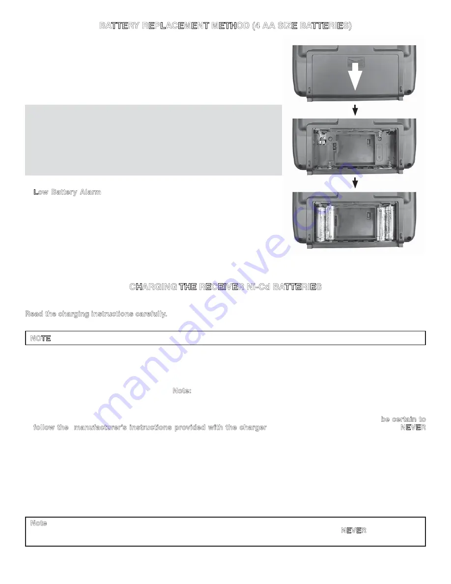
1. Remove the battery cover from the transmitter by sliding it in the direction of 

the arrow in the figure.

2. Insert four new AA size batteries.

3. Slide the battery cover back onto the case.

CAUTION

j 

Always be sure you reinsert the batteries in the correct polarity direction. If 
the batteries are loaded incorrectly, the transmitter may be damaged. 

j 

When the transmitter will not be used for any short or long period of time, 
always remove the batteries. If the batteries do happen to leak , clean the 
battery case and contacts thoroughly. Make sure the contacts are free of 
corrosion.

•   

Low Battery Alarm

: If the transmitter battery voltage drops below approx. 

4.2V, the red LED on the front of the transmitter will slowly blink. Land your 
model immediately before losing control.

CHARGING THE RECEIVER Ni-Cd BATTERIES

Ni-Cd batteries require special care and charging.

Read the charging instructions carefully.

NOTE

: The batteries are supplied partially charged, but will require a full, overnight charge before the model may be flown.

1. The receiver charging cord may be connected to the batteries two different ways: The charge cord may be connected 

directly to the battery pack, or to the vacant charge connector (black) coming from the on/off switch in the model. Charging 
“through the switch” is preferred as there will be no need to disconnect the battery.

2. Plug the A/C wall charger into a wall outlet. 

Note:

 If the wall outlet can be turned off by a switch in the room, be certain the 

switch remains on after leaving the room. Otherwise, the batteries will not be charged!

3. The charger’s LED (Light-emitting diode) should light red, indicating that current is flowing and the batteries are being 

charged. Discharged batteries will take about 15 hours to fully charge. If using an aftermarket fast charger, 

be certain to 

follow the  manufacturer’s instructions provided with the charger

 so you do not overcharge the batteries. 

NEVER


charge the batteries at a rate higher than 1,000mA. The batteries should also be discharged periodically to prevent a 
condition called “memory.” If, for example, only two flights are made each time you go flying, the batteries will not have 
“reached” very far down into their full capacity. After doing this several times the batteries will “remember” and eventually 
“think” they can supply only enough power for two flights. After two flights the batteries may not provide enough power to 
operate the system, thus causing a crash. To erase any potential memory, cycle the batteries by discharging, then charging 
them with a commercial battery cycler, or leave the system on and exercise the servos by moving the transmitter sticks 
until the servos are moving very slowly, indicating that the battery is discharged. Cycling should be done every one to 
two months, even during the winter or periods of long storage. If using a cycler with a readout, note the capacity after the 
batteries have been cycled. If there is a noticeable drop in capacity the batteries should be replaced.

Note

: Charging your batteries with the special Futaba A/C battery charger is always safe. However, fast-charging with 

an aftermarket charger is acceptable as long as you know how to properly operate the charger. 

NEVER

 charge at a rate 

higher than 1,000 mA (1 Amp). If not done correctly, fast-charging can damage the batteries.

Summary of Contents for 4YF-2.4GHZ

Page 1: ...TION MANUAL for Futaba 4YF 2 4GHz 4 channel FHSS Radio control system for Airplanes 1M23N11409 Futaba Corporation Technical updates available at http www futaba rc com Entire Contents Copyright 2009 4YF 2 4GHz ...

Page 2: ... become stuck continue to read on anyway SERVICE in USA If any difficulties are encountered while setting up or operating your system please consult the instruction manual first For further assistance you may also refer to your hobby dealer or contact the Futaba Service Center at the web site fax number or telephone number below www futaba rc com service futaba rc com Fax 217 398 7721 Telephone 8 00...

Page 3: ...e is to be approved by the laws governing the country of destination which govern devices that emit radio frequencies If this product is then re exported to other countries it may be subject to restrictions on such export Prior approval of the appropriate government authorities may be required If you have purchased this product from an exporter outside your country and not the authorized Futaba di...

Page 4: ...Aeronautics AMA which has more than 2 400 chartered clubs across the country Through any one of them instructor training programs and insured newcomer training are available Contact the AMA at the address or toll free phone number below Academy of Model Aeronautics 5161 East Memorial Drive Muncie IN 47302 Tele 800 435 9262 Fax 765 289 4248 or via the Internet at http www modelaircraft org j Always...

Page 5: ...use Failure to follow the proceeding precautions can quickly result in severe permanent damage to the batteries and its surroundings and possibly result in a FIRE nWARNING l Do not attempt to disassemble Ni Cd packs or cells l Do not allow Ni Cd cells to come in contact with moisture or water at any time j Always provide adequate ventilation around Ni Cd batteries during charge discharge while in ...

Page 6: ... s direction so the control responds correctly Throw When speaking of a control surface such as an elevator or aileron the throw is the distance the surface moves Control surface throw is usually measured at the trailing edge of the surface and is expressed in inches or millimeters The model in the diagram has 1 2 13mm of up elevator throw Throw can also refer to the distance a servo arm or wheel ...

Page 7: ...dder Aileron trim lever On Off switch Charging jack Servo reverse switch Transmitting signal Green on Red on Power Down Mode Green on Red fast blink Low Battery Alarm Green on Red slow blink DESCRIPTIONS Neck strap hook Mounting point for optional neck strap Aileron elevator control stick Operates the servos connected to channel 1 aileron and channel 2 elevator in the receiver Trim levers all Used...

Page 8: ...ise the batteries will not be charged 3 The charger s LED Light emitting diode should light red indicating that current is flowing and the batteries are being charged Discharged batteries will take about 15 hours to fully charge If using an aftermarket fast charger be certain to follow the manufacturer s instructions provided with the charger so you do not overcharge the batteries NEVER charge the...

Page 9: ...Receiver on off switch red colored plug Receiver Switch Harness To Battery Charging Jack Black Aileron Servo CH1 Elevator Servo CH2 Throttle Servo CH3 Rudder Servo CH4 Red Link Switch LED 1 Place the transmitter and the receiver close to each other within one 1 meter 2 Turn on the transmitter 3 Turn on the receiver 4 Push and hold the Link switch on the receiver 5 When the link is complete the LED...

Page 10: ... buzzing sound coming from a servo there is probably too much resistance in the control Find and correct the problem Even if there is no servo damage excess battery drain will result Use the mounting plate from the receiver on off switch as a template for the cutout and screw holes Mount the switch on the side of the fuselage opposite the engine exhaust and where it won t be inadvertently turned o...

Page 11: ...n Use the reversing function to reverse any servos necessary 2 Center the control stick 3 Place the servo arms on the servos so they are perpendicular to the pushrods see page 10 It is okay to cut off any unused servo arms 4 Connect the pushrods to the control surfaces Adjust the length of the pushrods until the control surfaces are centered when the servos are centered To Adjust the Trim Settings...

Page 12: ...GHz the trainer jack is in the center of the rear of the case Do not force the plug into the transmitter and note that the plug is keyed so it can go in only one way 6 Turn on the instructor s transmitter and the student s transmitter T4YF 2 4GHz Set the servo reversing and trims of the student s radio to match that of the instructor s 7 Turn on the receiver switch in the model Pull the trainer sw...

Page 13: ...o activate the Power Down Mode please turn on the transmitter while pushing and holding the Power Down switch on the transmitter continue holding the Power Down switch During this mode the RF power is reduced so the range test can be performed When this mode is active the red LED on the front of the transmitter starts fast blinking This mode continues for 90 seconds while holding the Power Down sw...

Page 14: ...ION To assure continued FCC compliance Any changes or modifications not expressly approved by the grantee of this device could void the user s authority to operate the equipment FCC Label Compliance Statement This device complies with Part 15 of the FCC Rules Operation is subject to the following two conditions 1 This device may not cause harmful interference and 2 This device must accept any inter...

Page 15: ... prior notice While this manual has been carefully written there may be inadvertent errors or omissions Please contact our service center if you feel that any corrections or clarifications should be made FUTABA CORPORATION 1080 Yabutsuka Chosei mura Chosei gun Chiba 299 4395 Japan Phone 81 475 32 6982 Facsimile 81 475 32 6983 FUTABA CORPORATION 2009 12 1 ...

Reviews: