V
FUTABA 9Z
THE UNOFFICIAL WORKSHOP MANUAL
WARNING:
THE INFORMATION IN THIS MANUAL IS FOR INFORMATION PURPOSES ONLY AND MAY BE INCORRECT, CAUSE DAMAGE
TO YOUR RADIO OR INJURY TO YOURSELF AND OTHERS. IF YOU USE THIS MANUAL YOU DO SO SOLEY AT YOUR OWN RISK.
www.jamesandtracy.co.uk
Copyright 2012 jamesandtracy.co.uk
Page 37 of 84
5.
Solder in the new battery pack
6.
Reassemble
You can test for a blown diode on the mini-PCB during the above operation just use the
diode test facility on your multimeter to make sure it passes current in only one direction.
However, as the stock diode is only 400mA and far too small for bullet proof charging
using modern equipment, it is suggested that even if the diode is functional you should
replace it by upgrading to a larger 3A version (see Section 4.7 for the procedure).
3.11. RF Module
The RF Module in the 9Zap is a TK variant, rather than the TP variant used in 8u’s and
9c’s. Although there are some posts on the internet suggesting otherwise (some even
from Futaba), to all intents and purposes these seem to be interchangeable for PPM
operation and a Futaba agent even confirms this in one positing. Certainly, I have used
both TK and TP variants in my 8u’s, 9c’s, 9VAP and 9ZAP without issues for PPM
operation. So whilst I’m not 100% certain, you can probably swap any one with any other
without issues as long as you’re using PPM. For PCM operation, you should probably
stick with the appropriate module for the transmitter.
One of the main issues with both TK and TP modules (and with aftermarket 2.4GHz
conversions), is the sudden loss of the ‘On Air’ LCD message and associated alarm
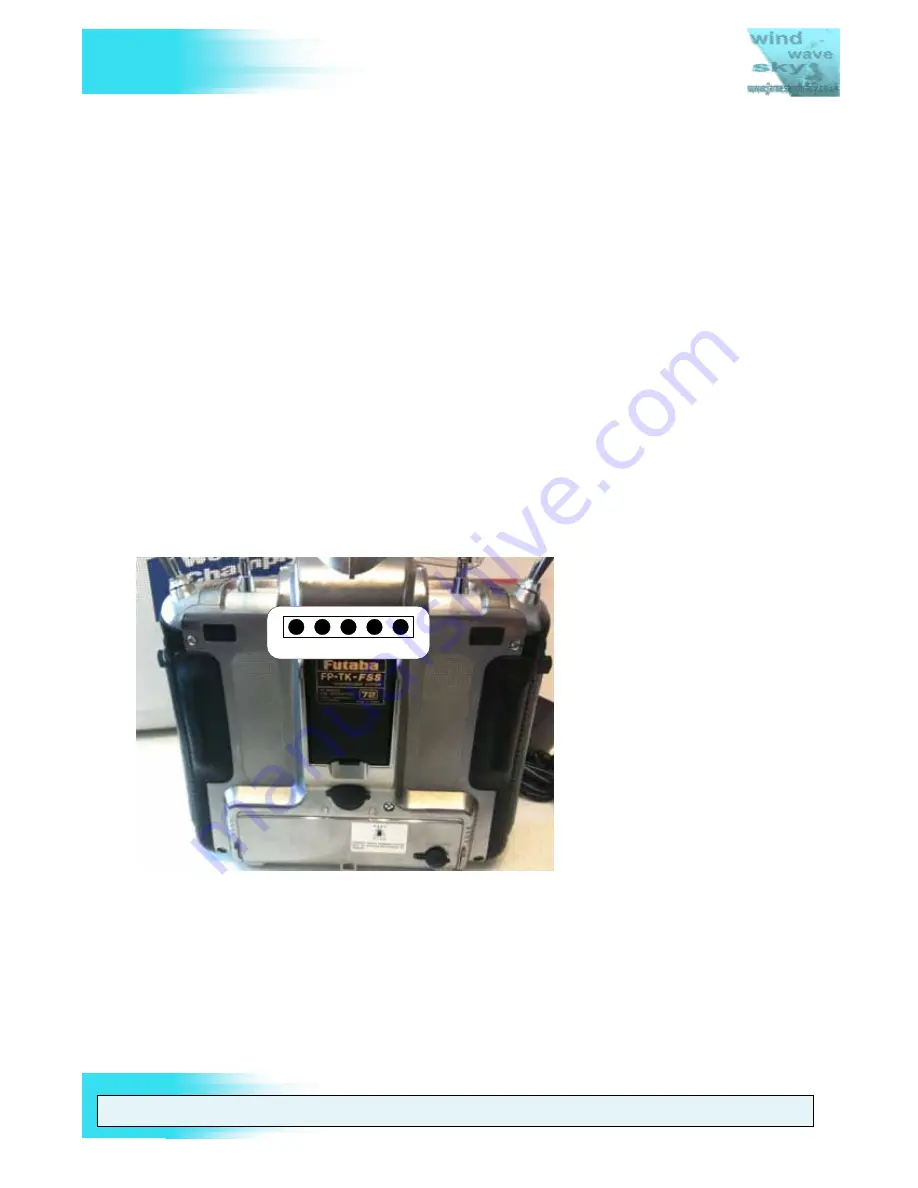
light. Futaba modules use the RF Pin-out shown in Figure 31 which is more fully
described in APPENDIX B.
1 RF PINOUT
5
Figure 31 Futaba RF Module Pin-out Numbering
Pin number 3 is the RF Output Indicator. This pulls to ground (Pin number 4) when RF is
detected. Connecting these two pins together tells the radio it is transmitting and causes
it to show the “On Air” LCD message and associated alarm light.


