V
FUTABA 9Z
THE UNOFFICIAL WORKSHOP MANUAL
WARNING:
THE INFORMATION IN THIS MANUAL IS FOR INFORMATION PURPOSES ONLY AND MAY BE INCORRECT, CAUSE DAMAGE
TO YOUR RADIO OR INJURY TO YOURSELF AND OTHERS. IF YOU USE THIS MANUAL YOU DO SO SOLEY AT YOUR OWN RISK.
www.jamesandtracy.co.uk
Copyright 2012 jamesandtracy.co.uk
Page 79 of 84
Pin-out functions:
1.
PCM/PPM Signal from Radio
2.
V+
3.
RF Output Indicator (Pulls to ground when RF is detected)
4.
GND
5.
RF Out
B.3. Futaba DSC/Trainer Pin-out Information
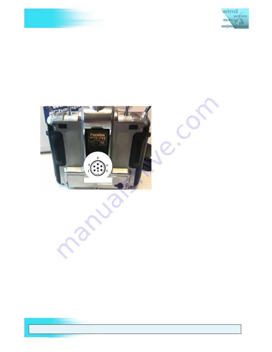
The connector in Figure 80 is a standard 6 pin DIN which is readily available from most
audio equipment and electronic component providers
DSC CONNECTOR
Figure 80 DSC/Trainer Port Pin-out (6 pin DIN)
DSC/Trainer Port Pin-Out configuration:
0.
(i.e. the metal shield) Ground
1.
+V batteries (Switched)
2.
Signal output
3.
Signal Input
4.
+V output
5.
+V Input (for powering up without RF Transmission)
6.
+5v Input (and is used by DSC-cable for receiver voltage information)
Note: Connecting pin 4 and 5 to each other will cause the transmitter to power up
without RF transmission when it is switched on. This is necessary for correct operation
of DSC and simulator cables.


