background image

20

CDR-5000 Functions

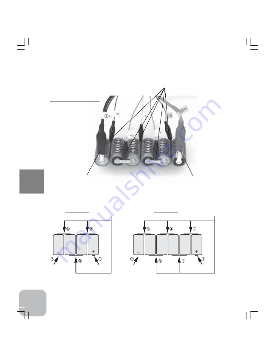
•Terminal Harness

*Connect Terminal Harness as shown here.

DX Terminal
  /Terminal Harness

•DX Terminal  (-)

*Black: negative

•DX Terminal  (+)

*Red: positive

(4 cells)

(6 cells)

•Terminal
    Harness

•Terminal
    Harness

•DX Terminal  (-)

•DX Terminal  (-)

•DX Terminal (+)

•DX Terminal (+)

Summary of Contents for CDR5000

Page 1: ... 12 to 16Vdc that have current overload protection circuit fuse If you use a power source whose current output capacity is less than the charging current you may damage the power source The guaranteed operating range of CDR 5000 is from 11V to 16V Don t use the car battery installed in a car Prepare a 12V standalone car battery for charging If you use the battery installed in your car the battery ...

Page 2: ...harging 15 1 Setting Parameters for Charging Discharging 15 2 Connecting Battery 19 3 Start of Charging Discharging 21 4 End of Charging Discharging 22 5 Cycle Charging Discharging 25 6 Compulsively End of Charging Discharging 26 Over Current Protection 27 Data Screen 28 1 DX DATA Screen 28 2 TX RX DATA Screen 32 Graph Screen 34 Warning Screen 41 Reference 43 Specifications 43 Option Parts 44 For ...

Page 3: ...e abnormally high heat generation and fire Never connect batteries in the wrong direction Wrong connection may cause the improper work of protection circuit and the excessive heat generation and may damage the CDR 5000 internal parts Never do an additional charging or discharging after the charging or discharging It is very dangerous to do so because the Auto cut will become unable to function and...

Page 4: ...eep them under the temperature in the range between 5 and 40 degrees Celsius while charging or discharging batteries Violation of this instruction may cause inadequate charging and discharging or may induce abnormal heat generation The Delta peak detection may not work properly when charging such batteries that are newly acquired or left unused for a long time Please stop charging when the tem per...

Page 5: ...perature and cause some danger The temperature of a battery exceeding over 60 degrees Celsius may cause very dangerous conse quences Electrolytic solution in a battery If electrolytic solution in a battery scatters into your eyes you may face a danger of losing your eyesight due to the strong alkaline characteristics of the electrolytic solution In such a case never scratch but immediately wash yo...

Page 6: ...rage discharge voltage internal relative resistance time power level matched level outside temperature humidity battery temperature input voltage and so on DX port The maximum voltage to stop charging can be set at 0 1 62V DX port The function of Zero delta volt 0DV is available Setting range 3mV 50mV cell for charging a NiCd battery DX port Independent terminal Terminal Harness will provide accur...

Page 7: ...s used for charging discharging batteries for transmitters Please make sure that polarity is correct before connecting the adaptor to TX TR terminal of CDR 5000 RX charge adaptor This is used for charging discharging batteries for receivers Please make sure that polarity is correct before connecting the adaptor to TX TR terminal of CDR 5000 Terminal harness This is used for measuring characteristi...

Page 8: ...ut clips Connect these to a battery for motors Be sure to connect in the proper polarity Red positive Black negative View from the left side of CDR 5000 Stand Always spread this stand while charging discharging for cooling TX RX charge adaptor terminal Red positive Black negative Please give full attention to the polarity View from the right side of CDR 5000 Terminal Harness connector Thermo stand...

Page 9: ...R 5000 will automatically turn on and show its opening screen When a battery is connected Keep the button pressed until INITIAL SETTING screen shows up SET UP screen will return to Data screen or Graph screen automati cally about one minute after no key operation is done Graph 1 screen is shown Keep the button pressed until INITIAL SETTING screen shows up ...

Page 10: ...11 CDR 5000 Functions Use Graph or key to advance to the next screen and use key for reverse ...

Page 11: ...ase contact to the distributor from whom you purchased the system How to reset the previous data While pushing and keys at the same time connect the input cord to the power source and switch on the power source and then CDR 5000 will be reset to the status as supplied by the factory How to switch from the opening screen to another screen INITIAL SETTING screen Push Set up key DX DATA screen Connec...

Page 12: ... will be shown on the opening screen The maximum number of characters is eight Characters to be used ABCDEFGHIJKLMNOPQRSTUVWXYZ abcdefghijklmnopqrstuvwxyz 0123456789 Operation keys Move cursor by pushing or keys to select the character Set character by pushing or keys FIRST CYCLE You can select Discharging or Charging to start the cycle mode that repeats charging and discharg ing up to the preset ...

Page 13: ...high during continuous cycles of charging and discharging under CYCLE MODE WARNING On the SET UP screen you can display confirmation messages or not by setting this parameter The default parameter is set to ON Setting mode ON Display confirmation messages OFF Do not display confirmation messages Operation key Push any one of and keys to select the mode BUZZER Set the buzzer ON or OFF The default p...

Page 14: ... the DX port push any of the following keys Data Graph Enter and in the opening screen to go to DX DATA screen Then push Set up key in the DX DATA screen to SET UP screen Confirmation and setting of parameters in the SET UP screen DX SET UP This screen is for DX port Rapid charge discharge batteries for motors TX RX SE UP This screen is for TX RX port Batteries for transmitters and receivers Opera...

Page 15: ...arge number of cells it is recommended to set the charge current within the maximum current shown in page 27 Example When charging a NiCd battery of 2400mAh typical the target charging current will be derived from the following calculation 2400mAh x 1 0 2 4A 2400mAh x 1 5 3 6A Therefore set the charging current in this case between 2 4A and 3 6A However in case of NiMH batteries it is recommended ...

Page 16: ...AX VOLT This is to set the maximum voltage of the battery to stop charging at DX port Setting range is from 0 1 through 62V 0 001V step If the WARNING is set to ON on the INITIAL SETTING the confirmation message CUT OFF MAX VOLT IS TOO HIGH will be shown on the screen when the voltage is set over 13V If there is no error continue setting The message will be shown no more than twice It is recommend...

Page 17: ...harging a battery of 1000mAh typical the target charging current should be lower than 1A 1000mAh x 1 0 1 0A Charging a battery at over 1C may cause abnormal heat generation or deterioration of the battery Never charge a battery at over 1C especially when the battery is connected to a transmitter SET DISCHARGE This is to set the discharging current at TX RX The setting range is from 0 1 to 5A 0 01A...

Page 18: ...at the polarity is correct Caution In case of discharging a battery of a transmitter do not try to discharge the battery while it is connected to the transmitter A pro tection circuit in a transmitter will prevent it The CDR 5000 is not applicable for discharging those batteries with protection circuit Examples NT 8A NT8S1100 for T9Z and so on DX port This port is for the batteries for motors that...

Page 19: ...nal Harness Connect Terminal Harness as shown here DX Terminal Terminal Harness DX Terminal Black negative DX Terminal Red positive 4 cells 6 cells Terminal Harness Terminal Harness DX Terminal DX Terminal DX Terminal DX Terminal ...

Page 20: ...dicator changes from READY to D CHG And discharging will start Caution for discharging Sensing the voltage of the battery while discharging at TX RX CDR 5000 automatically calculates the voltage level that stops discharging It sug gests that if you discharge a battery that has been already discharged or a battery whose voltage is already very low the battery will be over discharged Never do an add...

Page 21: ... 0 DELTA VOLT When DELTA PEAK was used for CHARGE CUT TEMP When battery temperature was used for CHARGE CUT VOLT When the maximum voltage was used for CHARGE CUT CAPA When charging capacity was used for CHARGE CUT LOW DC 12V When the voltages drop of a power source was used as a parameter for CHARGE CUT POWER LEVEL This is the number that represents the status of a battery under charging by calcul...

Page 22: ...m that is detected at first among the items related to DISCHARGE CUT in the SET UP screen VOLT When the voltage level was used for DISCHARGE CUT TIMER When timer was used for DISCHARGE CUT POWER LEVEL This is the number that represents the status of a battery under discharging by calculating from the voltage drop of the battery to which a certain constant load is applied The bigger the number is t...

Page 23: ...GE CUT is carried out in proper way by DELTA PEAK LOW DC 12V This message will be shown when CHARGE CUT is carried out by the drop of a power source Caution If the output voltage increases abnormally charging will be forced to stop as the FINISHED TX RX CHARGE screen will not be shown MODE indicator changes from CHARGE to READY with an alarm buzzer End of discharging at TX RX Alarm buzzer will bee...

Page 24: ... Discharge will be shown Those screens are exactly same as those shown in the single Charge and Discharge modes How to return to DX DATA screen Push Data key to return to DX DATA screen from FINISHED screen Cycle Charging Discharging at TX RX 1 Push TX RX CYCLE key 2 Either the blue LED of TX RX Discharging or the red LED of TX RX Charging turns on MODE indicator changes from READY to CYCLE01 And ...

Page 25: ...G and TX RX CYCLE in order to intentionally stop charging on the way at TX RX Then the MODE indicator changes from CHG to READY and the red LED of TX RX Charging turns off with a single beep If the BUZZER is set to OFF in the INITIAL SETTING there will be no alarm buzzer How to stop discharging on the way at TX RX Push any one of the keys of TX RX CHG TX RX D CHG and TX RX CYCLE in order to intent...

Page 26: ... at DX can be set at 0 1A to 40A in the SET UP screen the actual discharging current will vary depending on a battery voltage measured at its terminals 2 4V or less smaller than 40A 7 5V or less 40A Max 8 5V or less 35A Max 10V or less 30A Max 12V or less 25A Max 15V or less 20A Max 20V or less 15A Max 30V or less 10A Max 40V or less 7 5A Max 50V or less 6A Max 60V or less 5A Max greater than 60V ...

Page 27: ...be shown In case of cycle mode the data of one cycle in the column of CHARGE and DISCHARGE will be shown at a time on the same screen 01 represents the current cycle 02 represents the previous cycle 03 represents the two previous cycle And so on If the cycle mode has been carried out at the latest the charge and discharge data of the last cycle will be shown in the DX DATA 01 And the data of the p...

Page 28: ... by using the time consumed for discharging from the beginning to the end MIDDLE STAGE This shows the estimated average voltage of a battery at a middle stage of discharging process by using the time consumed for discharging from the beginning to the end LAST STAGE This shows the estimated average voltage of a battery at a late stage of discharging process by using the time consumed for dischargin...

Page 29: ... DATA02 10 SET AMPERE This shows the current for charging or discharging set in the SET UP CUT OFF VOLT This shows the voltage to stop charging or discharging set in the SET UP PEAK VOLT This shows the peak voltage of a battery that is obtained while the battery is charged AVERAGE VOLT This shows the average voltage of a battery that is obtained while the battery is charged or discharged FIRST STA...

Page 30: ...ging CAPACITY This shows the accumulated amount of charge or discharge that has been charged or discharged from the beginning TIME This shows the accumulated amount of time from the start of charging or discharging POER LEVEL This is the number that represents the status of a battery under charging or discharging by calculating from the voltage drop of the battery to which a certain constant load ...

Page 31: ...1 MODE This indicates the condition of a battery that is to be charged or discharged NO BAT No battery is connected READY A battery is connected Ready to start charging or discharging CHG The battery is now under charging D CHG The battery is now under discharging CYCLE01 99 Cycle charging discharging is now under operation SHORT This includes reverse connection of a battery electrical short over ...

Page 32: ...at has been charged or discharged from the beginning Contents of TX RX DATA02 10 SET AMPERE This shows the current that is preset for charging or discharging at the SET UP PEAK VOLT This shows the peak voltage of a battery that is obtained while the battery is charged Or the voltage of the battery to stop discharging CAPACITY This shows the accumulated amount of charge or discharge that has been c...

Page 33: ...is completed in cycle mode The messages on the top of the screen are from left to right Graph type or charging current appears alternatively while charging V output voltage B T temperature of the battery The messages on the bottom of the screen are from left to right AVE an average voltage at charging C charged amount T time consumed for charging How to operate A cursor line vertical to the time a...

Page 34: ... of the battery The messages on the bottom of the screen are from left to right AVE an average voltage at discharging C discharged amount T time consumed for discharging F average voltage at first stage M average voltage at middle stage L average voltage at last stage These values will be shown on the screen alternatively How to operate A cursor line vertical to the time axis will appear by pushin...

Page 35: ...are shown at the bottom on the screen How to operate A cursor line vertical to the time axis will appear by pushing key The cursor line can be moved left and right by pushing and keys The messages at the bottom of the screen will change when the cursor line appears From left to right on the bottom of the screen C cell number V the minimum and maximum voltage of the cell T the time at the crossing ...

Page 36: ... and discharging current appears alternatively while discharging V output voltage B T temperature of the battery CELL numbers 1 6 are shown at the bottom on the screen How to operate See page 36 for the operating instructions Pushing Graph or key in the GRAPH Screen Page4 will show the GRAPH Screen Page5 Pushing will show GRAPH Screen Page3 GRAPH Screen Page 5 TERMINAL HARNESS Pushing Graph or key...

Page 37: ...vel How to operate In order to check the data of each cell select the cell number by pushing Enter key The aver age charge voltage of each cell will be shown after cell number blinking at the bottom on the screen Pushing Enter key each time shows cell number sequentially from C1 C2 C3 C4 C5 C6 Pushing Enter key after C6 shows the average charging voltage for all cells Pushing Graph or key in the G...

Page 38: ... the GRAPH Screen Page7 will show the GRAPH Screen Page8 Pushing will show GRAPH Screen Page6 GRAPH Screen Page 8 DIS 6 AV CELL Pushing Graph or key in the GRAPH Screen Page7 will show the GRAPH Screen Page8 This bar graph shows the average voltages of each cell in discharging mode Not applicable to a battery of 7 cells or more Although no graphs will be shown during charging no data will be shown...

Page 39: ...N ºC TIME Pushing GRAPH or key in the GRAPH Screen Page8 will show the GRAPH Screen Page9 This bar graph shows temperature and humidity measured by Thermo Sensor built in CDR 5000 Graph type is shown on the screen At the bottom OUTSIDE TEMP temperature measured by the Thermo Sensor equipped with DR 5000 HUMID humidity How to operate A cursor line vertical to the time axis will appear by pushing ke...

Page 40: ...H BATTERY IS OVER HEATED This warning appears when the temperature of the Thermo Stand option exceeds 75 degrees Celsius Be careful since the battery is very hot The warning will be cleared as the temperature declines Pushing Data key can clear this warning INPUT POWER SUPPLY VOLTAGE IS TOO LOW This warning appears when the output voltage of a power source for charging drops Please check the outpu...

Page 41: ...to next procedure This message will appear no more than two times If the warning is set to OFF in the Initial setting this warning will not be displayed CUT OFF MAX VOLT IS TOO HIGH This message appears when the maximum battery voltage is set at over 13V for C CUT OFF MAX VOLT at DX in the SET UP screen Please confirm if there is no problem with the value before moving on to next procedure This me...

Page 42: ... 0 01A step 12 Battery Voltage 15V 0 1 20A 0 01A step 15 Battery Voltage 20V 0 1 15A 0 01A step 20 Battery Voltage 30V 0 1 10A 0 01A step 30 Battery Voltage 40V 0 1 7 5A 0 01A step 40 Battery Voltage 50V 0 1 6A 0 01A step 50 Battery Voltage 60V 0 1 5A 0 01A step 60 Battery Voltage 62V 0 1 4A 0 01A step TX RX port below 10V 0 1 5A 0 01A step above 10V 0 1 3A 0 01A step Discharge cut methods Detecti...

Page 43: ... Nakase Mihama ku Chiba 261 8555 Japan Phone 043 296 5119 Facsimile 043 296 5124 FUTABA CORPORATION 2004 01 Temperature Sensor This is for measuring temperature for monitoring the characteristics of a battery under charging or discharging and for stopping charging or discharging by the preset temperature Trimmer is located on the back of the Thermo Stand Connector This connector is used for connec...

Reviews: