background image

when desiring to make the spin and other steering
angles large, set it to ON and adjust the horn, ad-
justers, and trimmers for level flight.
When the dual travel switch is set to OFF, kick
up is set, and the steering angle becomes large.

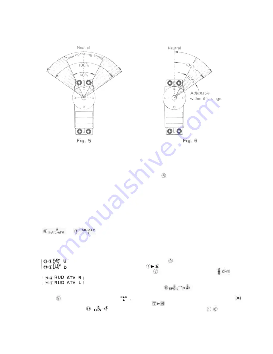
•Aileron, elevator, and rudder right and left (UP.

DOWN) angle adjustment

[ATV (Adjustable Travel Volume)]
The aileron, elevator, and rudder steering angles
can be made small within the range of the hatched
lines in Fig. 6.
When the aileron right roll and left roll rates are
different, they can be made the same by adjusting

the and trimmers of Fig. 2.

This also applies to the elevator and rudder. An
elevator UP and DOWN difference can also be
provided for easier flying.

The elevator ATV trimmers are

point, linkage is extremely simple.

Dual travel is operative even at elevator and flap
mixing.
Use the CH6 flap trim lever of Fig. 1 to adjust

the flap neutral position. Use this trimmer is the
same manner as a trim lever (aileron trim and
elevator trim).
Mixing is released when the MIX switch is set to
the center position (• mark). The flap neutral
position is not changed at this time.

(NOTE) Channel 6 is for the flaps, but can also be

used as a spare channel. However, since the
travel range is slightly narrow, adjust the

linkage.

•Adjustment when mixing spoiler, etc. and flaps

(When using the flaps and spoiler as an air brake)

Connect the flap servo to channel 6 of the re-

ceiver and the spoiler servo to channel 7.

of Fig. 2.

The rudder ATV trimmers are

of Fig. 2.

•Elevator and flap mixing adjustment

Connect the flap servo to channel 6 of the receiver.
When the MIX switch of Fig. 1 is set to

the elevator and flaps are mixed. Set the steering

When the MIX switch of Fig. 1 is set to

. the spoiler is mixed with the flaps. When

the CH7 switch of Fig. 1 is set to , the
spoiler and flaps are operated simultaneously.
The amount of mixing at this time is adjusted
with the trimmer of Fig. 2.
The direction and amount can also be set.
When the MIX switch is set from RELEASE
to , the flap neutral position may deviate.

If this occurs, adjust the NEUTRAL

trimmer of Fig. 2 so that the flap neutral position
does not change when the MIX switch is set to
any position.

Summary of Contents for FP-8JN

Page 1: ...Futaba DIGITAL PROPORTIONAL RADIO CONTROL ...

Page 2: ...portional radio control set Please readthis manual thoroughly before using your new set CONTENTS Features Contents and Ratings Transmitter Controls Using the Transmitter Using the Receiver and Servos Modules Warranty Repair and Adjustment Service ...

Page 3: ...can be freely adjusted Throttle button Throttle half can be freely adjusted Hook band is standard Since this transmitter has numerous accessories hanging it from your neck with this band makes operation easier Buit in antenna Locked when pulled up one stage stage Human engineered exterior Superior operability Receiver FP R8J Module type The frequency band and modulation method can be changed with ...

Page 4: ...rol 1520uS N One side 45 or greater including trim 4 8V 8mA when stopped 3 0kg cm 39 0 x 19 0 x 31 5mm 36g Receiver FP R8J Receiving frequency Intermediate frequency Power requirement Current drain Dimensions Weight Receiving range 27MHz 53MHz Bands 72MHz Band Selectable by changing modules 455kHz 4 8V 16mA 49 0 x 42 0 x 24 0mm 52g With FP T8JN trans mitter 500m on the ground 1000m in the air Serv...

Page 5: ... TRANSMITTER CONTROLS Fig 1 ...

Page 6: ...ects whether the operating angle is varied at the HIGH side of the stick or the LOW side of the stick when the maximum operating angle of the servo is adjusted with AIL ATV R This trimmer adjusts the aileron travel in the right direction when the aileron reverse switch is in the NORM position Travel is continuously variable from 50 to 100 of the total travel range AIL ATV L This trimmer adjusts th...

Page 7: ...g from the spoiler to the flap Travel range is the same as that of trimmer Elevator dual trimmer ELEV DUAL This trimmer adjusts the travel at elevator dual rate ON The travel is continuously variable from 40 to 100 of the total travel range Channel 6 flap neutral trimmer MIX NEUTRAL Elevator ATV U trimmer ELEV ATV U This trimmer adjusts the elevator travel in the UP direction when the elevator rev...

Page 8: ...nna is contracted and when it is extended fully The pointer indication will also be different when the antenna is grasped with your hand and when it is not grasped When the antenna is contracted the transmitter does not deliver an output even though the level meter pointer deflects DO NOT USE THE TRANSMITTER UNDER THIS STATE Push the battery check switch The level meter pointer will indicate the b...

Page 9: ...ng is released when the MIX switch is set to the center position mark The flap neutral position is not changed at this time NOTE Channel 6 is for the flaps but can also be used as a spare channel However since the travel range is slightly narrow adjust the linkage Adjustment when mixing spoiler etc and flaps When using the flaps and spoiler as an air brake Connect the flap servo to channel 6 of th...

Page 10: ... Snap roll B Fig 1 S ROLL B This is similar to snap roll A The direction and amount of aileron elevator and rudder are set with the trimmer of Fig 2 Using snap roll button A for right snap roll and snap roll button B for left snap roll is extremely convenient Adjust to match the aircraft The snap roll buttons may also be used as spin buttons Using the aileron elevator throttle and rudder reverses ...

Page 11: ... USING THE RECEIVER SERVOS Aileron servo ...

Page 12: ...nge and attaching it to the fuselage with rubber bands the same as the receiver All the servos can be controlled from the receiver direct servo control system by applying the signals form the transmitter to terminal C of the receiver In this case the transmitter current drain will drop to about 1 4 that when transmitting Connect the intermediate cord with lug to ter minal C and fastening it to the...

Page 13: ...ear 3rd gear Final gear 2nd shaft Intermediate shaft Output shaft Spacer washer Seal ring Radial ball bearing Pan head screw Truss screw Motor Slider Volume Grommet Name plate Fiber washer Servo horn Toothed washer Phillips pan head screw E ring 0 ring Quantity 1 1 1 1 1 1 1 1 1 1 1 1 1 2 4 2 1 1 1 1 1 2 1 1 1 Remarks M2x24 M2x5 16 M2 M2x5 Fig 11 ...

Page 14: ...itting and receiving modules with the 72 080 MHz RF module EXAMPLE 3 Switching from 72 240MHz to 53 400MHz AM Replace both the transmitting and receiving modules with the 53 400 MHz AM RF module EXAMPLE 4 Switching from 72 080MHz to 53 200MHz FM Replace both the transmitting and receiving modules with the 53 200 MHz FM RF module and also replace the receiver with an FM receiver EXAMPLE 5 Switching...

Page 15: ...ctions given below 1 Charge the batteries for at least 18 hours prior to shipment 2 Return the system only Not your complete installation Remove the servos from their mounts and remove the foam padding from the receiver 3 Plugs or other modifications which interfere with factory test procedures will be returned to factory standard at your expense 4 Carefully pack all components individually using ...

Page 16: ......

Reviews: