31
< Before Use >
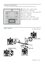
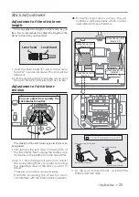
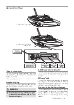
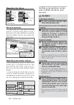
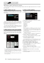
Link/Mode Switch
8
se the small plastic screw driver that was
included with your receiver.
The
/
ink/Mode Switch is also used for the CH
mode selection.
Extra Voltage Connector
8
se this connector when using a voltage
telemetry device to send the battery voltage
DC
a
9
from the receiver to the transmitter.
<
ou will need to purchase the optional
(
xternal
9
oltage input cable
CA-R
9
I
1
-
.
<
ou can then make a cable with an extra
connector to the
(
xternal voltage connector.
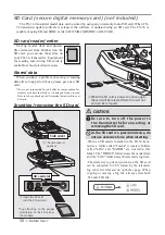
%
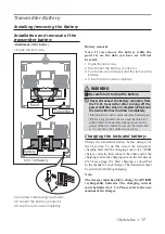
efore using the receiver
be sure to read the
precautions listed in the following pages.
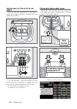
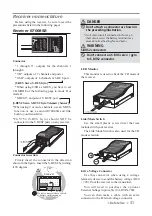
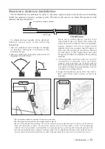
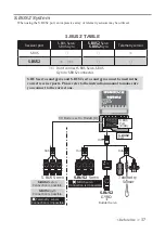
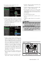
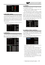
ŵƈƆƈƌƙƈƕŃŵŚœœśŶť
Connector
through 6
: outputs for the channels
through 6
/
%
: outputs of
channels and power.
/S
%
: outputs of
channels or S.
%8
S port.
>
S.BUS Servo S.BUS
*
yro
@
*
:
hen using
/S
%
as S.
%8
S
you have to set
CH M
2
D
(
of the following page to mode
%
or
mode D.
S.
%8
S2
: outputs of S.
%8
S2 port.
>
S.BUS2 Servo S.BUS2
*
yro Telemetry Sensor
@
*
:
hen using
or more channels
use an S.
%8
S
function or use a second R
S
%
and link
both to your transmitter.
*CG
<
S.
%8
S Gyro
should
12
T be
connected to the S.
%8
S2 ports on any receiver.
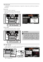
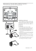
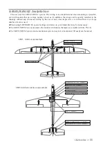
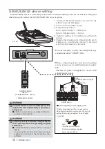
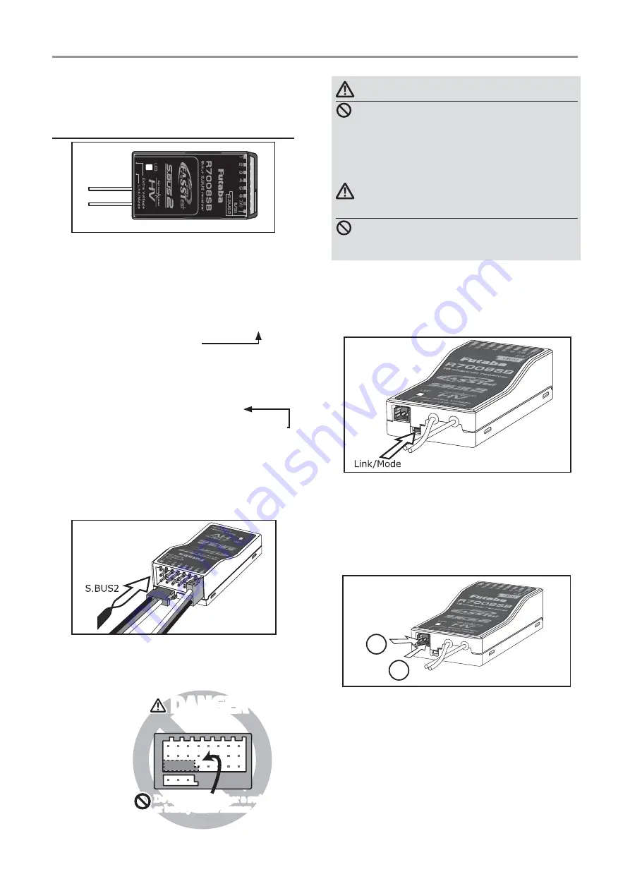
Connector insertion
Firmly insert the connector in the direction
shown in the
¿
gure. Insert the S.
%8
S2 by turning
it
degrees.
+
−
Do not connect either a switch
or battery in this manner.
Do not connect either a switch
or battery in this manner.
5HFHLYHU
DANGER
DANGER
DANGER
Don't attach a connector as shown in
the preceding illustration.
*It will short-circuit if connected in this way. A
short circuit across the battery terminals may
cause abnormal heating, fire and burns.
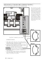
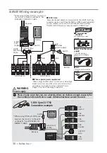
WARNING
S.BUS2 connectors
Don't connect an S.BUS servo / gyro
to S.BUS2 connector.
LED Monitor
This monitor is used to check the CH mode of
the receiver.
ŵƈƆƈƌƙƈƕŃƑƒƐƈƑƆƏƄƗƘƕƈ


