69
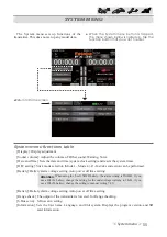
< Linkage menu >
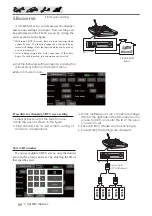
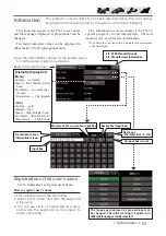
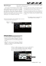
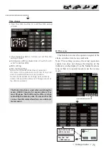
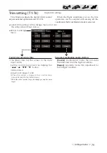
Model type
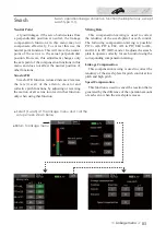
This function selects the model type from among airplane, glider,
helicopter, and multicopter.
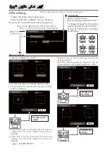
( The display screen is an example. The
screen depends on the model type.)
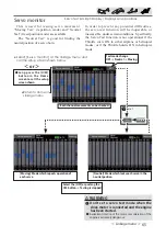
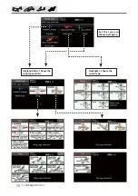
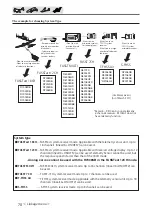
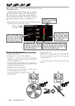
Seven types of main wings (six types of
À
ying
wing) and three types of tail wings are available
for airplanes. Eight swash types are available
for helicopters. Seven types of main wings and
three types of tail wings are available for gliders.
Functions and mixing functions necessary for each
model type are set in advance at the factory.
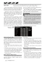
Note: The Model Type function automatically selects
the appropriate output channels, control functions,
and mixing functions for the chosen model type.
When the Model Type Selection command is
accessed, all of the data in the active memory is
cleared. Be sure that you don
·
t mind losing this data,
or back it up to another memory using the copying
functions.
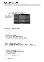
ŏ
Select [Model type] at the linkage menu and call
the setup screen shown below.
ŏ
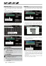
When a data change will occur, the confirmation
screen of data initiali
]
ation menu will be displayed.
A push on [yes] will initiali
]
e data and allow changes.
A push on [no] will stop data changes.
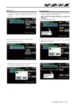
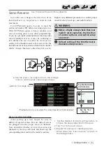
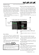
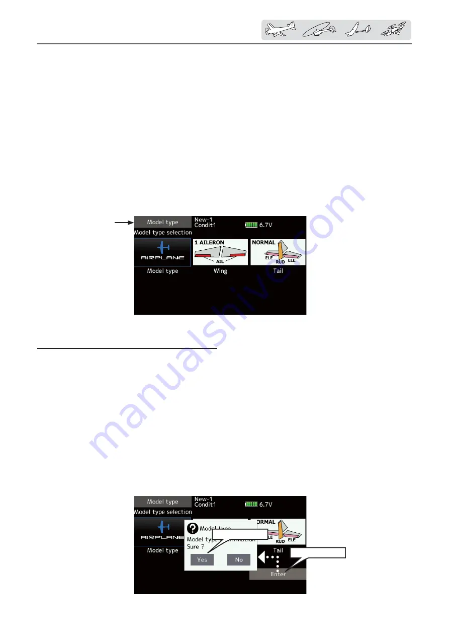
Model type selection
1. Model type selection [Model icon], tap.
2. Set the Model type, Wing type(Airplane/
Glider), Tail type(Airplane/Glider), or Swash
type(Helicopter) by using the appropriate
button.
3. Set the type you choose by tapping
[Enter]
→
[Yes] at the confirmation screen.
(When you want to cancel model type
selection, tap [No].)
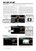
ŏ
Return to Linkage
menu
1. [Enter], tap
2. [Yes], tap


