33
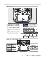
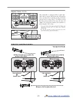
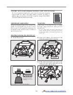
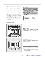
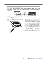
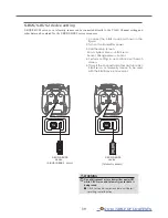
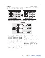
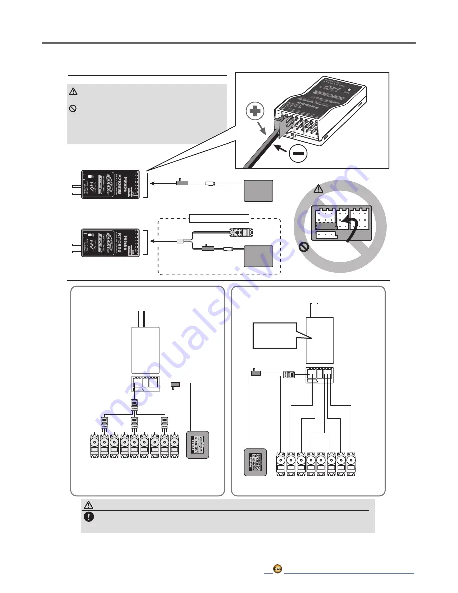
Connection of a receiver battery
Connection example
Battery
3.7 ~ 7.4 V
Switch
Servo
Y-harness
When all ports are used.
Battery
3.7 ~ 7.4 V
Switch
A battery is connectable
also with which port.
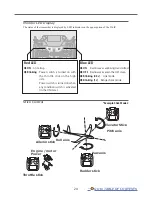
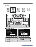
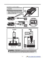
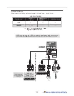
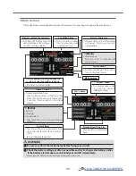
R7108SB
Channel 1-8
Conventional servos
Battery
PWM
Battery
HUB
HUB
S.BUS servos
Channel 1 -18
Switch
Switch
to 8/SB port
S.BUS
R7108SB
CH Mode
→Mode A
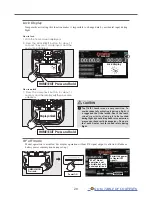
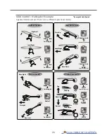
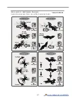
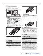
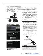
WARNING
Please make sure that you use a battery
that can deliver enough capacity for the
number and kind of servos used. Dry
batteries cannot be used.
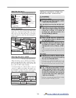
Power supply
Please make sure that you use a battery that can deliver enough capacity for
the number and kind of servos used. Alkaline batteries cannot be used.
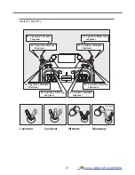
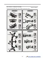
WARNING
Receiver
Do not insert either a switch
or battery in this manner.
DANGER
Summary of Contents for T16IZ
Page 1: ...1M23Z07702 WEB FULL MANUAL ...
Page 228: ......


