background image

MANUAL

 250.120RC – DISTY 120RC [EN]


V1.0 – 09.2022


INSTRUCTION MANUAL [EN] 
 
250.120RC 

– DISTY 120RC 


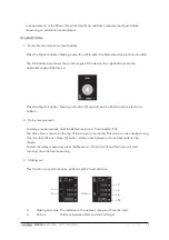
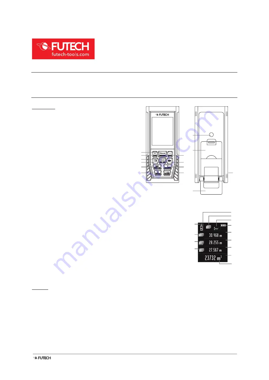
OVERVIEW 


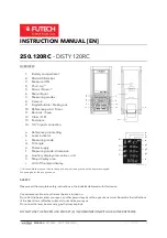
1.


Battery compartment 

2.


Micro USB socket 

3.


Measure / ON 

4.


Plus / Up 

(*)


5.


Minus / Down 

(*)


6.


Menu/Equal 

7.


Measuring modes 

8.


Camera 

9.


Digital bubble / Staking-out 

10.


Reference point / Timer 

11.


Records  / Save  

12.


Clear / OFF 

13.


End piece  

14.


1/4” tripod connection 


a.


Reference point setting 

b.


Laser indicator 

c.


Measuring mode 

d.


Tilt angle 

e.


Power supply 

f.


Measuring mode: dimension 

g.


Auxiliary display area: value + unit 

h.


Major display area 

i.


Unit of the major display. 


(*) It is possible that on your device the up and down arrows printed on the keys are swapped.  

We apologise for the inconvenience. 


SAFETY 


Please read the complete safety instructions in the booklet delivered with this device. 

Use extreme caution when the laser beam is turned on.  

Do not let the beam enter your eyes, another person’s eyes or the eyes of an animal. Be careful that reflections 
of the beam (on a reflective surface) do not strike your eyes.  
Do not aim the laser beam at any gas that may explode.  

DO NOT USE THE MICRO USB SOCKET [2] IN COMBINATION WITH ALKALINE BATTERIES.


DISTY

120

RC

1

11

2

14

13

9

7

6

4

12

10

8

5

3

a

c

d

e
g

³

g

²

g

¹

h

f

³

b

f

²

f

¹

i

Summary of Contents for 250.120RC

Page 1: ...h Major display area i Unit of the major display It is possible that on your device the up and down arrows printed on the keys are swapped We apologise for the inconvenience SAFETY Please read the co...

Page 2: ...g used the meter will be turned off automatically after 150 seconds This setting can be changed in the menu SETTINGS Enter the menu by pressing the Menu Equal button 6 The settings menu will be visibl...

Page 3: ...calibration Turn off the device Hold the Records Save button 11 and press the measure ON 3 button shortly The device will start up Release the Records Save button 11 after the start up screen has dis...

Page 4: ...Continuous measurement minimum maximum Hold the Measure On 3 and focus on the target point To know the minimum and maximum distance slightly move the focus left right up down During measuring the act...

Page 5: ...display area g3 Press the Measure On button 3 a second time to measure the second side Length of side 2 appears on auxiliary display area g2 Press the Measure On button 3 a third time to measure the...

Page 6: ...n secondary display g3 the previously measured walls move up one place each time After each additional wall measured the Major display area h will show the new updated total area of all walls measured...

Page 7: ...pears on the auxiliary display area g2 Press the Measure ON button 3 a second time to measure the length of one side a The length of side a appears on the auxiliary display g1 The Major display Area h...

Page 8: ...on of c Press the Measure ON button 3 to measure the length of the first side a The length of side a appears on the auxiliary display area g3 Press the Measure ON button 3 a second time to measure the...

Page 9: ...auxiliary display g1 The Major display Area h shows the length of l2 the part between auxiliary line l1 and hypothenuse c 10 Area of an irregular triangle based on 3 sides Calculate area of an irregul...

Page 10: ...ears in front of the major display area h Measure the second distance as described above The last measurement appears on auxiliary display g3 the result of the calculation will be visible on the major...

Page 11: ...t 3 Volume measurement To add a measurement to this result press the Plus Up button 4 The result of the previous measurement disappears a appears in front of the major display area h To subtract a mea...

Page 12: ...g out button 9 again to exit the Multi direction electronic bubble 2 Delay measurement To delay a measurement hold the Reference point Timer button 10 The delay time is shown on the top of the screen...

Page 13: ...lus Up 4 and Minus Down 5 button to set value a Confirm with the Measure ON button 3 Use the Plus Up 4 and Minus Down 5 button to set value b Confirm with the Measure On button 3 Place the device in i...

Page 14: ...a in single measuring mode Make the cross which is on the screen point exactly your target Press the measuring ON button 3 to measure the distance The result will be visible in the Major display area...

Page 15: ...nction will be shown on the Mayor display area h 5 Angle values on top of the screen The device shows the tilt angle d The range of this angle is always between 90 0 and 90 0 The unit which can be cho...

Page 16: ...ex Yes Optional units m inch ft Addition Subtraction of measurements Yes Maximum Minimum values Yes Staking Out Yes Delay measurements Yes Self calibration Yes Angle of tilt 90 Multi direction electro...

Reviews: