- 28 -
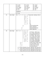
0 1 0 0 Al1 Hi active, Al2 Lo active
0 1 0 1 Al1 Lo active, Al2 Lo active
0 1 1 0 Al1 disabled, Al2 Lo active
1 0 0 0 Al1 Hi active, Al2 disabled
1 0 0 1 Al1 Lo active, Al2 disabled
1 0 1 0 Al1 disabled, Al2 disabled
0 0
Al1 & Al2 non-latching
0 1
Al1 latching, Al2 non-latching
1 0
Al1 non-latching, Al2 latching
1 1
Al1 & Al2 latching
0 0 Relay1 On when Al1 active, Relay2 On when Al2 active
0 1 Relay1 Off when Al1 active, Relay2 On when Al2 active
1 0 Relay1 On when Al1 active, Relay2 Off when Al2 active
1 1 Relay1 Off when Al1 active, Relay2 Off when Al2 active
00 (U)
Serial Cnfg4
(NG to review
carefully)
Bit 7 6 5 4 3 2 1 0 Serial Protocol
0
0 No Parity
0
1 Odd Parity
0 0
Custom ASCII protocol (8 bits)
0 1
Modbus RTU protocol (8 bits)
1 0
Modbus ASCII protocol (7 bits)
0 0
1 s Modbus ASCII gap timeout
0 1
3 s Modbus ASCII gap timeout
1 0
5 s Modbus ASCII gap timeout
1 1
10 s Modbus ASCII gap timeout
8.2 DPM 3-BYTE RAM MEMORY DATA
Format for all items except Scale Factor: MS byte Mid byte LS byte
XX
XX
XX
Format for Scale Factor:
*X
XX
XX
The 4-bit MS nibble “*” sets the polarity and decimal point according to the following table:
Positive
Negative
Decimal Point
1
2
3
4
5
6
9
A
B
C
D
E
XXXXX....
XXXX....X
XXX....XX
XX....XXX
X....XXXX
....XXXXX
Note:
Hex values are 2's complement and absolute values.


