background image

 12 

5.  Mark the location of the center of the beam near the 

first mark so that both marks are in line, one above 
the other. 


6.  At 100 ft., the marks should be no more than ¼” 

apart. 

At 50 ft., the marks should be no more than 1/8” 

apart. 


This is within the stated accuracy of 

±

 1/8” at 100 ft. 

(

±

 0.01%). 


7.  If the marks are close enough, X axis is within 

calibration. The second axis (Y) must then be 
checked (see later section). 


If the marks are not close enough, the X axis needs to 
be calibrated (see below). 


U

Calibrating X axis 


The laser must be calibrated to bring the beam to the 
center of the two X marks. Calibration is electronic, using 
the keys on the remote control.  


Follow the directions carefully, as once you move the 
beam while in the calibration mode, you cannot cancel 
and return to the original position. 


1.  To put the laser in calibration mode, simultaneously 

press the backlight key (12) and X / Y key (15). A 
blinking symbol H over a point appears on the 
display  (27) to indicate that you are calibrating a 
horizontal axis. 


2.  Press the rotation key (18) and choose a rotation 

speed with the multi key (10). If it’s too bright to see 
the beam, use a detector, or put in scan mode. Note 
that the H symbol (27) has stopped blinking. 


3.  Press the X/Y key (15) to re-activate the calibration 

mode. The H symbol will blink again. 

4.  If you have not moved the laser, use the X marks 

made in Steps 3 & 5 of “Checking X axis.” Mark the 
spot that’s halfway between the two marks. 


5.  Use the left   and right   arrows on the multi key 

(10) to move the beam to the halfway mark. If +X is 
facing the wall, the right arrow moves the beam up 
and the left arrow, down.  


U

CAUTION:

 Do NOT use the up or down arrows.

U


Summary of Contents for LT600

Page 1: ...jobs Other advanced features include totally automatic self leveling in both horizontal and vertical modes electronic calibration by the user and a detachable keypad that can be used as a remote cont...

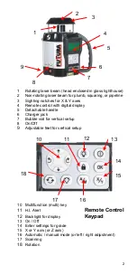
Page 2: ...5 Detachable handle 6 Charger jack 7 Bubble vial for vertical setup 8 On Off 9 Adjustable feet for vertical setup 10 Multifunction multi key 11 H I Alert Remote Control 12 Backlight for display Keypa...

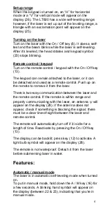
Page 3: ...munication status between laser remote control or backlight indicator UHOW TO USE THE LT600 Setup UHorizontal The laser can be used on a 5 8 11 tripod on a wall mount or directly on a solid stable sur...

Page 4: ...rom the laser There is two way communication between the laser and the remote control If the remote is within range and properly communicating with the laser an antenna will appear on the display 28 I...

Page 5: ...22 will blink on the display To start the laser rotating again press key 11 for 3 seconds the lock symbol should stop blinking The head may have re leveled itself to a new position Check to see if the...

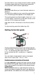
Page 6: ...e rotation key 18 Setting horizontal grade The two horizontal axes X and Y are marked near the base of the laser The ends of the axis are designated as or to indicate opposite sides of the axis Do not...

Page 7: ...t B are 120 ft apart Rod reading at A is 5 ft at B 6 ft Difference in elevation 1 ft Divide 1 by 120 00833 x 100 833 B is lower than A so it s a negative grade USelecting percent of grade X Y axes 1 T...

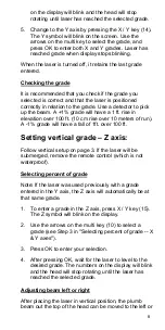
Page 8: ...e will have a fall of 1ft over 100 ft Setting vertical grade Z axis Follow vertical setup on page 3 If the laser will be submerged remove the remote control which is not waterproof USelecting percent...

Page 9: ...Laser battery The LT600 has a NiMh rechargeable battery that should be charged for 15 hours before first use A battery symbol on the display 24 indicates the battery charge Important If the battery ch...

Page 10: ...partment on the back of the remote UCHECKING AND ADJUSTING THE LT600 THIS CHAPTER IS VERY IMPORTANT Here are a few simple instructions to check your LT600 for calibration Remember that the laser is a...

Page 11: ...Y needs calibration calibrate Y proceed to X to Y check Final X to Y check compare X X Y Y Check Z and calibrate if necessary UChecking X axis 1 Place the laser on a flat surface or tripod 50 or 100 f...

Page 12: ...bration mode you cannot cancel and return to the original position 1 To put the laser in calibration mode simultaneously press the backlight key 12 and X Y key 15 A blinking symbol H over a point appe...

Page 13: ...re than apart At 50 ft marks should be no more than 1 8 apart This is within the stated accuracy of 1 8 at 100 ft 0 01 6 If the marks are close enough Y axis is within calibration Proceed to Final X t...

Page 14: ...5 to exit calibration mode This will also turn the laser off Turn the laser on again and do Final X to Y Check UFinal X to Y Check As a final check of the horizontal axes compare X and Y axes to each...

Page 15: ...refully as once you start moving the beam while in the calibration mode you cannot cancel and return to the original position 1 To put the laser in calibration mode simultaneously press the backlight...

Page 16: ...on After it has self levelled mark the location of the beam on the near wall a Always mark the centre of the beam If it s too bright to see the beam use a detector 3 Rotate the laser 180 Mark the loca...

Page 17: ...the instrument has been subjected to shock will void this warranty Under no circumstances will the liability of the manufacturer exceed the cost of repairing or replacing the instrument Disassembling...

Page 18: ...LT 600 Universal Laser Dual Grade Pipe Laser Ceiling Laser Plumb Laser Right Angle Squaring Including Remote Control Instruction Manual...

Page 19: ...Your Authorised Dealer Futtura Paderborn Germany...

Reviews: