background image

Operation

Power:

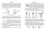
 Press the power switch on the touch panel to turn the 

unit on. All the LED's will light briefly, then each LED grade 

display row will turn on then turn off from top to bottom. Then 

each status indicator will turn on and off. The current deadband 

status and on grade location will momentarily display. If the 

receiver is out of a laser beam, the center green LED will flash to confirm power 

is on. If the receiver is in a laser beam, a corresponding LED grade display 

will be indicated. 
While the unit is on, pressing and holding the power switch and then pressing 

the touch panel switches will activate secondary functions which are indicated 

by the symbols above the switch.
To turn the power off, press and hold the power key until the LED's are lit, then 

release. Settings will be retained the next time the unit is turned on. 

Switch Functions

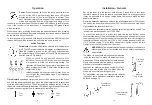
Tilt Indicator

: Press the tilt indication switch to turn the display on 

or off. The LED status indicators will display a rolling sequence. 

When the function is turned on, the LED's will  sequence from 

the center outward. When turned off, the LED's will sequence 

from the outer LED's inward.

When  on,  the  LED's  will  provide  5  channels  of  tilt 

indication. The center LED will be on when the blade 

or  dipperstick  is  within  the  tilt  accuracy  setting. The 

right side will light when the operator's right side of the 

blade or dipperstick is low. The left side will light when 

the left side is low. 
Initially the blade tilt indication is set to level. It can be 

set to match the current blade slope. See installation 

notes on Page 15. 

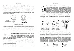
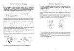
Tilt Indicator Accuracy

: Accuracy can be set to fine, standard or wide. Press 

and hold the power switch and then press the tilt indicator switch to select and 

cycle the tilt accuracy function. The current selection will flash rapidly. Pressing 

this switch combination while the status LED is flashing will change the current 

selection, sequencing from fine to standard to wide to fine, etc. 

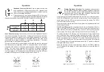
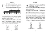
Fine

± 0.5º

Standard

± 1.5º

Wide

± 2.5º

8

13

Installation - General

Set  up  the  laser  in  a  convenient,  safe  location.  Please  refer  to  your  laser 

operator's manual. Ensure the laser is on a stable tripod. On windy, gusty days 

it may be advisable to tie down or weigh down the tripod to make the laser 

beam more stable.
Operating distances are dependent upon the rotating laser power.


The receiver 

can pick up the beam from all directions (360°), but still requires a clear line of 

sight between the laser and receiver. 
If your laser has selectable rotation speeds, select a high rotation speed. The 

receiver can process speeds up to 1200 RPM.
To  mount  the  receiver  on  a  mast,  turn  both  the  top  and  bottom  knobs 

counterclockwise until the mounting clamps in back open enough to fit around 

the mounting mast. Place the receiver on the mast. The receiver will mount to 

round tubing that has a 42 to 50 mm (1.66" to 2.00") outside diameter or to 38 mm  

(1-1/2") square tubing. Turn the knobs clockwise to tighten. Loosen the two 

clamps to remove the receiver from the mast.

WARNING:

 Follow all safety precautions per the machines operator's 

manual and follow all excavation and trench safety requirements 

and practices.

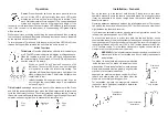
Typical dozer

installation

Typical excavator

installation

The blade tilt and plumb indications are measured 

inside the receiver. The blade tilt indicates side-to-

side position. Plumb indicates front-to-back position. 

Masts and receivers must be properly aligned to the 

machinery for accurate indications.
Assure dozer masts are aligned vertical both front-

to-back  and  side-to-side  with  the  blade  when  the 

blade is in its normal operating position.
For  excavation,  typically  the  mast  points  towards 

the bucket teeth. Additional installation details can 

be found on page 15.

Plumb axis

rotation

Blade tilt

axis rotation

Summary of Contents for MCR2+

Page 1: ...Laser Receiver Model MCR2 Operator s Manual P N 010751 15 Rev C Manual ...

Page 2: ... work manship for a period of two years This warranty period is twenty four months from the date the product is delivered from the dealer to the purchaser or is put into service by a dealer as a demonstration unit or rental unit Please retain your product information and proof of purchase Proof of purchase must accompany your request for warranty repair Any evidence of abuse misuse alteration acci...

Page 3: ...aser Receiver Safety 2 System Description 3 Controls and Displays 4 Battery Installation Charging 6 Operation 8 Installation and Set Up 13 Specifications 18 Warranty 19 Maintenance and Care 19 010806 Rev D Notes ...

Page 4: ...o service as a demonstration or rental unit Please retain your warranty information and proof of purchase Any evidence of abuse misuse alteration accident or negligent use or an attempt to repair products by unauthorized personnel or with parts other than those provided by the manufacturer automatically voids the warranty The user of the product is expected to follow all operating instructions per...

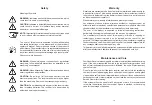
Page 5: ...atus LED s provide five channels of blade tilt indication and low battery indication in addition to selection status A tough sealed waterproof housing is designed to work in the tough machine mounted environment The electronics are isolated from the rest of the unit by internal rubber shock mounts protecting the unit from shock and vibration damage 18 3 Specifications Beam Reception 360 degrees Op...

Page 6: ...nch Set Up Set the laser up in an appropriate location for receiver visibility and efficient machine operation and turn it on Place the bucket in the grade checking position and situate the machine so a measurement can safely be obtained on the dipper arm The dipper arm may be set more horizontal to the ground for convenient measurements if necessary Determine the distance from the laser to the bo...

Page 7: ...ermined In Trench Set Up Position the machine and dig to the desired finished elevation Position the bucket in the grade checking position at the finished elevation Set the laser up in an appropriate location for receiver visibility and efficient machine operation and turn it on Mount the mast on the side of the dipper arm Point the mast at the bucket teeth as illustrated if checking grade with th...

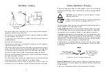
Page 8: ...e accessory connector is pointing upwards Remove the dust cap from the accessory connector Loosen the two thumb screws and remove the battery access cover Install four C cell batteries as shown on the label diagram inside the battery compartment noting the and terminals Replace the battery access cover Firmly tighten the two thumbscrews Ensure the battery access cover is aligned and fully engaged ...

Page 9: ...ng fully charged There is also protection to prevent charging alkaline batteries CAUTION Do not attempt to charge alkaline or other disposable batteries NOTE DonotchargeNi MHbatterieswhenambienttemperature exceeds 113 F 45 C or is less than 32 F 0 C The rechargeable battery electronics include a charge status and charge error indicator located on the back of the housing Charge Status Indicator The...

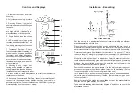
Page 10: ...ection will flash rapidly Pressing this switch combination while the status LED is flashing will change the current selection sequencing from fine to standard to wide to fine etc Fine 0 5º Standard 1 5º Wide 2 5º 8 13 Installation General Set up the laser in a convenient safe location Please refer to your laser operator s manual Ensure the laser is on a stable tripod On windy gusty days it may be ...

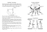
Page 11: ...grade LED s used Fine 0 5º Standard 1 5º Wide 2 5º Solid LED s Slow Flashing Fast Flashing 9 12 Operation Out of Beam Indication The receiver has an Out Of Beam OOB indication that can be turned on or off When it is on the LED grade display will indicate if the receiver has moved beyond the vertical laser reception range A sequence of LED s will indicate which direction to move the blade or cuttin...

Page 12: ...Averaging OFF 11 10 Operation Display Brightness Selection The brightness switch controls the LED grade display and blade tilt display brightness Bright and Dim are the selection options Use Bright for daytime operation if necessary and Dim for lower light conditions Operating with Display Dim selected will extend battery life When the brightness switch is pressed and the receiver is out of the la...

Page 13: ...Averaging OFF 11 10 Operation Display Brightness Selection The brightness switch controls the LED grade display and blade tilt display brightness Bright and Dim are the selection options Use Bright for daytime operation if necessary and Dim for lower light conditions Operating with Display Dim selected will extend battery life When the brightness switch is pressed and the receiver is out of the la...

Page 14: ...grade LED s used Fine 0 5º Standard 1 5º Wide 2 5º Solid LED s Slow Flashing Fast Flashing 9 12 Operation Out of Beam Indication The receiver has an Out Of Beam OOB indication that can be turned on or off When it is on the LED grade display will indicate if the receiver has moved beyond the vertical laser reception range A sequence of LED s will indicate which direction to move the blade or cuttin...

Page 15: ...ection will flash rapidly Pressing this switch combination while the status LED is flashing will change the current selection sequencing from fine to standard to wide to fine etc Fine 0 5º Standard 1 5º Wide 2 5º 8 13 Installation General Set up the laser in a convenient safe location Please refer to your laser operator s manual Ensure the laser is on a stable tripod On windy gusty days it may be ...

Page 16: ...ng fully charged There is also protection to prevent charging alkaline batteries CAUTION Do not attempt to charge alkaline or other disposable batteries NOTE DonotchargeNi MHbatterieswhenambienttemperature exceeds 113 F 45 C or is less than 32 F 0 C The rechargeable battery electronics include a charge status and charge error indicator located on the back of the housing Charge Status Indicator The...

Page 17: ...e accessory connector is pointing upwards Remove the dust cap from the accessory connector Loosen the two thumb screws and remove the battery access cover Install four C cell batteries as shown on the label diagram inside the battery compartment noting the and terminals Replace the battery access cover Firmly tighten the two thumbscrews Ensure the battery access cover is aligned and fully engaged ...

Page 18: ...ermined In Trench Set Up Position the machine and dig to the desired finished elevation Position the bucket in the grade checking position at the finished elevation Set the laser up in an appropriate location for receiver visibility and efficient machine operation and turn it on Mount the mast on the side of the dipper arm Point the mast at the bucket teeth as illustrated if checking grade with th...

Page 19: ...nch Set Up Set the laser up in an appropriate location for receiver visibility and efficient machine operation and turn it on Place the bucket in the grade checking position and situate the machine so a measurement can safely be obtained on the dipper arm The dipper arm may be set more horizontal to the ground for convenient measurements if necessary Determine the distance from the laser to the bo...

Page 20: ...atus LED s provide five channels of blade tilt indication and low battery indication in addition to selection status A tough sealed waterproof housing is designed to work in the tough machine mounted environment The electronics are isolated from the rest of the unit by internal rubber shock mounts protecting the unit from shock and vibration damage 18 3 Specifications Beam Reception 360 degrees Op...

Page 21: ...o service as a demonstration or rental unit Please retain your warranty information and proof of purchase Any evidence of abuse misuse alteration accident or negligent use or an attempt to repair products by unauthorized personnel or with parts other than those provided by the manufacturer automatically voids the warranty The user of the product is expected to follow all operating instructions per...

Page 22: ... work manship for a period of two years This warranty period is twenty four months from the date the product is delivered from the dealer to the purchaser or is put into service by a dealer as a demonstration unit or rental unit Please retain your product information and proof of purchase Proof of purchase must accompany your request for warranty repair Any evidence of abuse misuse alteration acci...

Page 23: ...aser Receiver Safety 2 System Description 3 Controls and Displays 4 Battery Installation Charging 6 Operation 8 Installation and Set Up 13 Specifications 18 Warranty 19 Maintenance and Care 19 010806 Rev D Notes ...

Page 24: ...Laser Receiver Model MCR2 Operator s Manual P N 010751 15 Rev C Manual ...

Reviews: