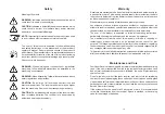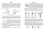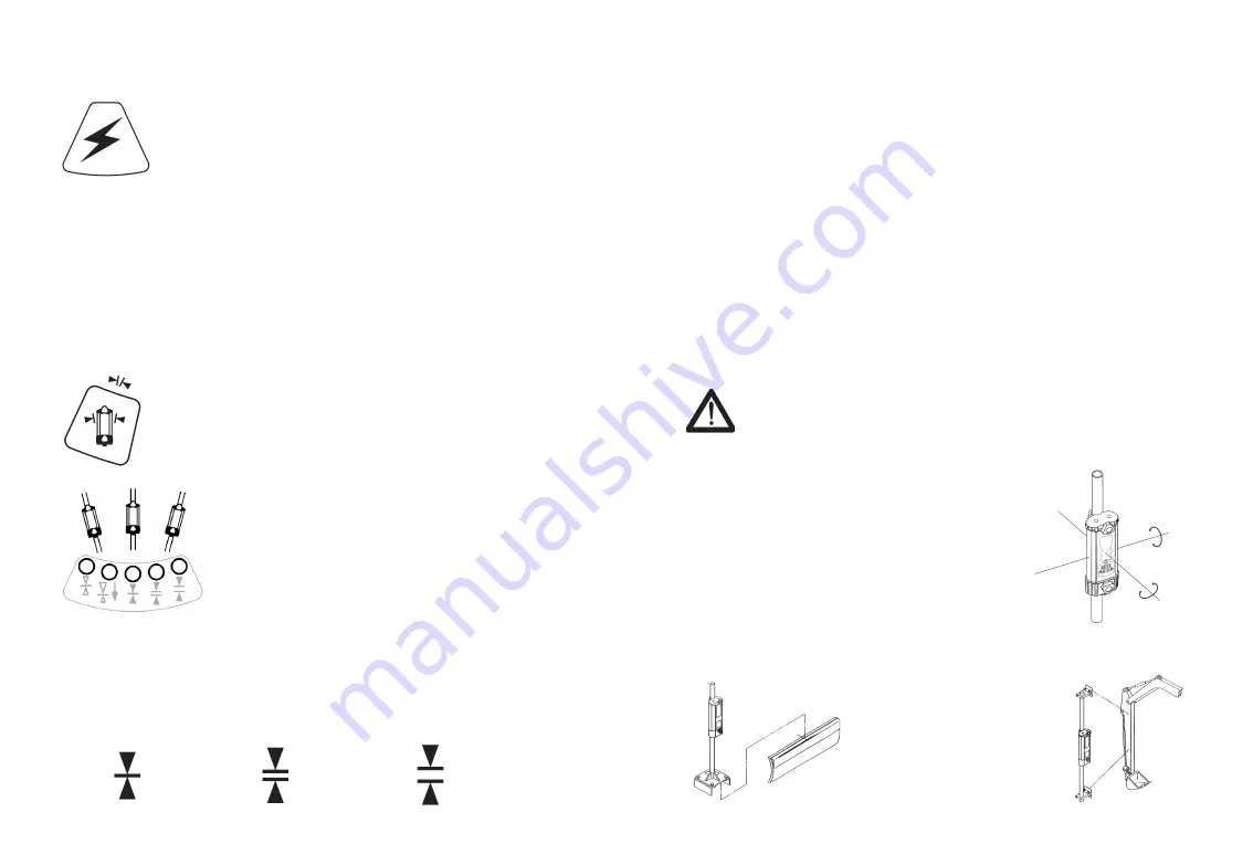
Operation
Power:
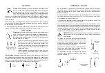
Press the power switch on the touch panel to turn the
unit on. All the LED's will light briefly, then each LED grade
display row will turn on then turn off from top to bottom. Then
each status indicator will turn on and off. The current deadband
status and on grade location will momentarily display. If the
receiver is out of a laser beam, the center green LED will flash to confirm power
is on. If the receiver is in a laser beam, a corresponding LED grade display
will be indicated.
While the unit is on, pressing and holding the power switch and then pressing
the touch panel switches will activate secondary functions which are indicated
by the symbols above the switch.
To turn the power off, press and hold the power key until the LED's are lit, then
release. Settings will be retained the next time the unit is turned on.
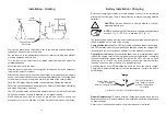
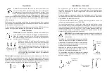
Switch Functions
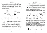
Tilt Indicator
: Press the tilt indication switch to turn the display on
or off. The LED status indicators will display a rolling sequence.
When the function is turned on, the LED's will sequence from
the center outward. When turned off, the LED's will sequence
from the outer LED's inward.
When on, the LED's will provide 5 channels of tilt
indication. The center LED will be on when the blade
or dipperstick is within the tilt accuracy setting. The
right side will light when the operator's right side of the
blade or dipperstick is low. The left side will light when
the left side is low.
Initially the blade tilt indication is set to level. It can be
set to match the current blade slope. See installation
notes on Page 15.
Tilt Indicator Accuracy
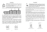
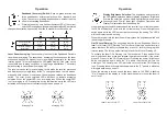
: Accuracy can be set to fine, standard or wide. Press
and hold the power switch and then press the tilt indicator switch to select and
cycle the tilt accuracy function. The current selection will flash rapidly. Pressing
this switch combination while the status LED is flashing will change the current
selection, sequencing from fine to standard to wide to fine, etc.
Fine
± 0.5º
Standard
± 1.5º
Wide
± 2.5º
8
13
Installation - General
Set up the laser in a convenient, safe location. Please refer to your laser
operator's manual. Ensure the laser is on a stable tripod. On windy, gusty days
it may be advisable to tie down or weigh down the tripod to make the laser
beam more stable.
Operating distances are dependent upon the rotating laser power.
The receiver
can pick up the beam from all directions (360°), but still requires a clear line of
sight between the laser and receiver.
If your laser has selectable rotation speeds, select a high rotation speed. The
receiver can process speeds up to 1200 RPM.
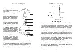
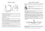
To mount the receiver on a mast, turn both the top and bottom knobs
counterclockwise until the mounting clamps in back open enough to fit around
the mounting mast. Place the receiver on the mast. The receiver will mount to
round tubing that has a 42 to 50 mm (1.66" to 2.00") outside diameter or to 38 mm
(1-1/2") square tubing. Turn the knobs clockwise to tighten. Loosen the two
clamps to remove the receiver from the mast.
WARNING:
Follow all safety precautions per the machines operator's
manual and follow all excavation and trench safety requirements
and practices.
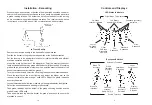
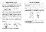
Typical dozer
installation
Typical excavator
installation
The blade tilt and plumb indications are measured
inside the receiver. The blade tilt indicates side-to-
side position. Plumb indicates front-to-back position.
Masts and receivers must be properly aligned to the
machinery for accurate indications.
Assure dozer masts are aligned vertical both front-
to-back and side-to-side with the blade when the
blade is in its normal operating position.
For excavation, typically the mast points towards
the bucket teeth. Additional installation details can
be found on page 15.
Plumb axis
rotation
Blade tilt
axis rotation


