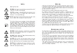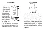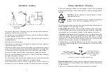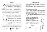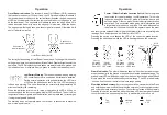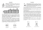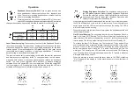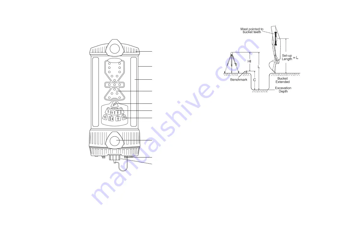
1. Aluminum cast upper and lower
housings.
2. Polycarbonate housing - protects
the electronics.
3. Receiving Window - four sets of
photocells spaced to allow 360 degree
reception.
4. Super-bright grade display LED's
are highly visible - graphically dis-
plays the blade or bucket position.
5. Power Switch turns the unit on
and off.
6. LED status indicators for on-grade
location, deadband selection, and
low battery warning. Also functions
as blade tilt indicator.
7. Touchpanel Switches - Primary
functions select blade tilt display, on-
grade location, on-grade deadband
(accuracy), and display brightness.
Secondary functions select blade tilt
accuracy, plumb indication accuracy,
laser beam averaging, and laser out-
of-level warning.
8. Mounting Knobs - large, front
facing knobs attached to stainless
steel clamps allow for quick and easy
installation to mast or magnetic mount.
9. Access screws - allows easy access to battery compartment for
replacement of batteries.
10. Accessory Connector and Dust Cap - connector accepts the cable
connector to the optional remote display, machine power cable, or
automatic control box. Connector also accepts Ni-MH battery charger.
Dust cap helps keep the connector clean.
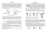
1
2
3
7
8
4
5
6
9
10
Controls and Displays
4
17
Installation - Excavating
Out of Trench Set-Up
Set the laser up in an appropriate location for receiver visibility and efficient
machine operation and turn it on.
Place the bucket in the grade checking position and situate the machine so a
measurement can safely be obtained on the dipper arm. The dipper arm may be
set more horizontal to the ground for convenient measurements if necessary.
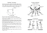
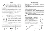
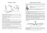
Determine the distance from the laser to the bottom of the trench (L). This is
the set-up length. The length is the height of the instrument (HI) plus the depth
of cut from the benchmark to the bottom of the trench (C).
Mount the mast on the side of the dipper arm. Point the mast at the bucket
teeth as illustrated if checking grade with the bucket fully extended. (If checking
grade with the bucket curled or other position, point the mast to the point of the
bucket that makes contact with the ground.)
Position the receiver so the set-up length (L) is the distance from the bucket
ground contact point to the offset on-grade symbol on the back label. (Set up
to center on-grade symbol if center on-grade will be used).
Turn the receiver on and select offset on-grade and the desired deadband.
Adjust the plumb indication accuracy if desired. (Select center on-grade if set
to center symbol).
Begin to excavate. Take grade readings with the bucket in the grade checking
position and the grade display LED's solid.
Take a sample reading with the bucket "on-grade" and check to ensure the
elevation is correct.


