13
Installation - Excavating
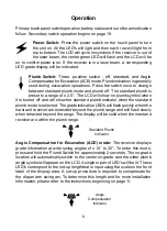
Angle Compensation for Excavation (ACE):
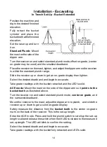
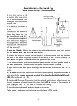
Use the length determined by
the set-up procedure described on pages 14 to 17.
Press and hold the plumb switch to enter the ACE mode and the set-up length
entry mode.
The on-grade location will automatically switch to the center on-grade and the
wide plumb (ACE) symbol will appear on the LCD.
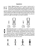
Single or pairs of LED's are lit and cycled up the scale as the switch is held.
Release the switch when the LED's are closest to the set-up length. An LED
blink will confirm the settings in approximately 2 seconds.
Example:
If the set-up length measurement was 84 inches, the switch would
be released when the pair of LED's are lit between the 80 and 100 inch marks
on the right side scale. (If the set-up measurement was 2.13 meters, the switch
would be released between the 2.00 and 2.50 meter marks on the left side
scale.)
The LED's will blink briefly to confirm the setting selected.
If the set-up number is passed, simply continue to press the switch until it
is cycled to the correct number again. The number may also be selected by
pressing and releasing the switch while in the set-up length entry mode. The
LED's will change one increment each time the switch is pressed. Release the
switch for to accept the displayed set-up length. An LED blink will confirm the
settings in approximately 2 seconds.
If the set-up length measurement is exactly a number on the scale, simply set
to the next higher number on the scale.
100 inch mark
80 inch mark
2.00 meter mark
2.50 meter mark
Set-up length between
80 and 100 inches
Set-up length between
2.00 and 2.50 meters
Summary of Contents for MCR3
Page 1: ...Laser Receiver Model MCR3 Operator s Manual...
Page 26: ......

