16
Installation - Excavating
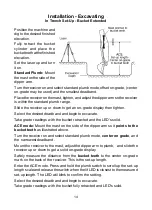
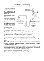
Out of Trench Set-Up - Bucket Extended
Fully retract the bucket cylin-
der and position the machine
so a measurement can safely
be obtained on the dipper
arm.
Set the laser up and turn
it on.
Determine the distance from
the laser to the bottom of the
trench (L). This is the set-
up length. The length is the
height of the instrument (HI)
plus the depth of cut from the
benchmark to the bottom of
the trench (C).
Standard Plumb:
Mount the mast on the side of the dipper arm so it
points
to the bucket teeth
as illustrated above.
Position the receiver so the set-up length L is the distance from the bucket
teeth to the offset on-grade symbol on the back of the receiver. (Set up to the
center on-grade symbol if center on-grade will be used).
Turn the receiver on and select standard plumb mode, offset on-grade, and the
desired deadband. (Select center on-grade if set to center symbol).
Begin to excavate. Take grade readings with the bucket retracted and the
LED's solid.
ACE mode:
Follow the procedure above except the set-up length is the dis-
tance from the
bucket teeth
to the
center on-grade
symbol on the back of
the receiver.
Enter the ACE mode. Press and hold the plumb switch to scroll up the set-up
length scale and release the switch when the lit LED is closest to the measured
set-up length. The LED will blink to confirm the setting.
Select the desired deadband and begin to excavate.
Take grade readings with the bucket retracted and LED's solid.
Summary of Contents for MCR3
Page 1: ...Laser Receiver Model MCR3 Operator s Manual...
Page 26: ......

