background image

3

System Description

The laser receiver is a rugged, multipurpose, electronic receiver that detects 

laser light generated by rotating laser transmitters. The unit works with nearly 

all models of rotating lasers and will detect both visible and invisible beams. 

When installed, the operator is given visual indication of the reference plane of 

laser light’s position relative to the cutting edge or digging depth of the machine. 

The receiver can also be installed with a Control Box for automatic control on 

certain grading machines. 

The operator can adjust the settings of the receiver to meet job site requirements. 

Settings are provided for adjusting the dead-band size or accuracy, on-grade 

location for grading or excavation, display brightness and more.

The  ultra-bright,  built-in  LED  display  provides  up  to  8  channels  of  grade 

elevation position, plus high and low lost beam indications.

Built in plumb indication allows for quick and accurate grade checks. The new 

Angle Compensation for Excavators (ACE) mode also allows grade checking 

at extended dipper arm swing angles once a simple set-up procedure is 

completed.

A tough sealed waterproof housing is designed to work in the tough machine 

mounted environment. The electronics are isolated from the rest of the unit 

by internal rubber shock-mounts, protecting the unit from shock and vibration 

damage.

Summary of Contents for MCR3

Page 1: ...Laser Receiver Model MCR3 Operator s Manual...

Page 2: ...that have been designed into it Please read this manual thoroughly before using your receiver Pleasecontactyourdealershouldyouhavequestionsregardingspeci c applications or if you require additional i...

Page 3: ...ty 2 System Description 3 Controls and Displays 4 Battery Installation Charging 6 Operation Primary Functions 8 Installation General 11 Grading 12 Excavating 13 Operation Secondary Functions 19 Mainte...

Page 4: ...s performance The manufacturer or its representatives assume no responsibility for results of the use of this product including any direct indirect consequential damage and loss of pro ts Check your...

Page 5: ...ceivertomeetjobsiterequirements Settings are provided for adjusting the dead band size or accuracy on grade location for grading or excavation display brightness and more The ultra bright built in LED...

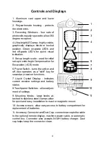
Page 6: ...the unit on and off Also operates as a shift key for secondary receiver functions 7 Liquid Crystal Display Indicates current receiver settings and battery status 8 Touchpanel Switches allow adjust men...

Page 7: ...Deadband Selection Display Brightness Selection Communication Link Not Used Touch Panel Lock Touch Panel Touch Panel Lock Out of Level RPM Indication Averaging 1 2 4 Display Brightness Selection Accu...

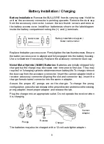
Page 8: ...eries are initially shipped fully charged but the charge may decrease over time prior to rst use They may require 2 or 3 charging cycles to obtain maximum battery life To charge remove the dust cap fr...

Page 9: ...If the batteries seem to be in a totally drained state initially the charge circuit will try to gradually charge the batteries If charging is unsuccessful after approximately 20 minutes the LED will t...

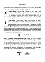
Page 10: ...ned off and will show the standard plumb indicator when the standard plumb mode is selected The grade indication LED s will ash quickly when the mast and receiver are extended beyond the plumb range a...

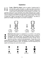
Page 11: ...us 2 out of beam indications The offset on grade has 8 display channels plus 2 out of beam indications Deadband Accuracy Four deadbands are available in the grading and excavating modes The LCD indica...

Page 12: ...replaced The battery symbol outline and the four corner LED s will ash to indicate the batteries require replacement or charging OutofBeamIndication TheLEDdisplay willindicateifthereceiverhasmoved bey...

Page 13: ...r from the mast For excavation the receiver may be set up in the trench or above ground Please follow all safety precautions per the machines operator s manual and follow all excavation and trench saf...

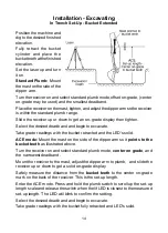
Page 14: ...to adjust the height of the laser Alternatively iftheheightofinstrument laserbeam to nishedelevationlengthis known the receiver can be set by measuring this distance from the cutting edge of the blad...

Page 15: ...0 inch marks on the right side scale If the set up measurement was 2 13 meters the switch would be released between the 2 00 and 2 50 meter marks on the left side scale The LED s will blink brie y to...

Page 16: ...e readings with the bucket retracted and the LED s solid ACE mode Mount the mast on the side of the dipper arm so it points to the bucket teeth as illustrated above Turn the receiver on and select sta...

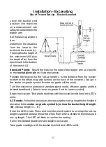
Page 17: ...dings with the bucket levelled and the LED s solid ACE mode Mount the mast on the side of the dipper arm so it points to the bucket pivot pin as illustrated above Turn the receiver on and select stand...

Page 18: ...he offset on grade symbol on the back of the receiver Set up to the center on grade symbol if center on grade will be used Turn the receiver on and select standard plumb mode offset on grade and the d...

Page 19: ...he back of the receiver Set up to the center on grade symbol if center on grade will be used Turn the receiver on and select standard plumb mode offset on grade and the desired deadband Select center...

Page 20: ...both hands place the top edge of the magnet on the machine Slowly move the bottom magnet towards the machine so the mount remains plumb or in the necessary set up position CAUTION Strong magnetic eld...

Page 21: ...t of level is disabled When the laser RPM drops to the selected laser out of level speed an X symbol will appear on the LED grade display and on the LCD symbol BeamAveraging Pressandholdthepowerswitch...

Page 22: ...anel lock function on and off When on the lock symbol is displayed on the LCD Switches cannot be changed and accidental changes from dirt or debris knocking the switches are prevented To make changes...

Page 23: ...protective case and normal instrument precautions are followed the unit will provide many years of service Do not wipe dust or dirt off the laser receiver with a dry cloth as scratching could occur po...

Page 24: ...play Output Bright Dim or Off Power Options Alkaline 4 x C Cell Standard Nickel Metal Hydride 4 x C Cell Power Cable 10 30 VDC Battery Life Alkaline 75 hours Display Dim Continuous in beam 50 Hours Di...

Page 25: ...sonnel or with parts other than those provided by the manufacturer automatically voids the warranty The user of the product is expected to follow all operating instructions periodically checking the i...

Page 26: ......

Reviews: