Installation
Position the RD15 in the machine's cab so the operator can
easily see the LED display during machine operation. Assure it
does not obstruct other operator functions. The RD15 includes an
assortment of mounting hardware including magnets, double-sided
tape, mating Velcro strips, and a rubber strap. Holes are provided
on the mounting plate for user provided hardware if necessary.
An optional swivel mount is available. Choose the appropriate
mounting hardware for your particular situation to secure the display
in a convenient viewing location.
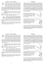
NOTE:
The RD15 has a vented
drain hole in the bottom of the unit near the cable connector that
must face downward.
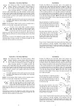
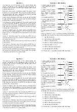
Magnet installation:
Install the provided
screw through the magnet and through
the mounting plate tab as shown. Secure
with the provided nut and tighten. Repeat
for the other side.
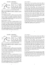
Mounting strap:
Install a hole of the
rubber strap around a mounting strap
tab. Wrap the strap around a suitable
support and secure the other end of
the strap around the other strap tab.
Ensure there is a snug fit.
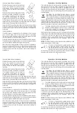
Tape / Velcro:
Double sided sticky tape and mating Velcro strips
allow mounting on various surfaces of the machine. Peel off
the protective backing of the adhesive side(s) and apply to the
appropriate clean location on the back of the remote display and
then a clean machine surface.
3
10
Operation - Function Switches
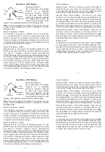
Set Temporary Offset:
The Set Temporary Offset
function allows a current laser strike location to
become the second temporary on-grade location.
This is useful for temporarily raising or lowering the
offset on-grade location. To activate, position the
receiver to the desired temporary offset elevation while receiving
a laser strike. Press the right side Select Function switch 2 times.
The second LED from the top will light. Press the left side Set
Function switch one time to set (press for less than 2 seconds
to avoid turning off).
The grade indication will now show green on-grade and
the amber Offset Elevation LED will flash if the command
is accepted.
NOTE:
The Temporary Offset function will not operate when a
MCR3 is in the angle compensation (ACE) mode.
To return to the initial offset on-grade location,
press the right side Select Function switch three
times. The third LED from the top will light. Press
the left side Set Function switch one time to set
(press for less than 2 seconds to avoid turning off). The amber
Offset Elevation LED will turn solid confirming return to the offset
location.
Alternatively, to return to the default on-grade location, press the
right side Select Function switch four times and press the left
side Set Function switch one time to set.

