background image

2

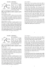
General Description

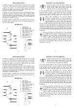
The RD15 is designed to work with MCR receivers. It is mounted 

in  the  cab  of  the  machine  for  easy  viewing  by  the  machine 

operator.  The  LED's  of  the  RD15  display  grade  information 

similar to the LED's of the receiver. Please refer to the receiver 

manual for specific displays and settings.
In addition to the standard grade, plumb, and tilt displays where 

applicable, the RD15 provides functions to set an offset elevation 

and a second temporary offset elevation on the receiver. An audio 

jack is provided for earphones. Tilt indication can be displayed for 

the MCR2+ and MCR3 receivers.
The  RD15  power  is  supplied  from  the  batteries  of  the  receiver. 

Optional  cables  supply  power  from  the  machine  battery  or  a 

machine power outlet.

8

9
10

1

2

2

3

3

5

6

7

4

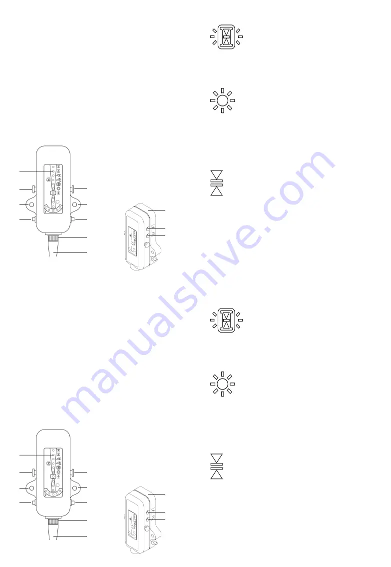
1.   LED Display

2.   Mounting Strap Tabs

3.   Mounting Plate Tabs

4.   Power / Set Function Switch

5.   Select Function Switch

6.   Cable Connector

7.   Communication Cable

8.   Mounting Plate

9.   Power Jack (3.5mm)

10.  Audio Jack (2.5mm)

Identification

11

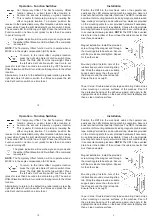
Operation - Function Switches

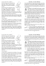
Receiver LED's On/Off:

 This function allows the 

receiver's LED's to be turned off and on. Turning 

off  the  receiver  LED's  will  conserve  battery  life 

when the receiver is powered by batteries. 

To turn the receiver LED's on or off, press the right side Select 

Function  switch  5  times.  The  fifth  LED  from  the  top  will  light. 

Press  the  left  side  Set  Function  switch  one  time  to  set.  The 

receiver LED's will turn off if they were on or on if they were off. 

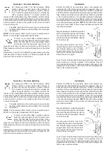
RD15  LED  Brightness:

  The  remote  display 

brightness can be adjusted to suit user preferences 

and light conditions. The default setting is medium 

(6/8)  brightness.  To  adjust,  press  the  right  side 

Select Function switch 6 times. The sixth LED from 

the top will light. Press the left side power switch to change the 

brightness. 8 levels of brightness are selectable. Each press will 

increase the brightness one level. The brightness will roll over to 

the dimmest display after the maximum display. After 4 seconds 

of no switch activity, the brightness will be set at the last selected 

brightness.

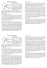
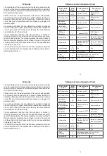
Deadband  Selection  (for  MCR2E  only): 

The  deadband 

for the MCR2E with Version 5 software (which is normally 

adjusted  by  a  control  box)  can  be  adjusted  using  the 

RD15.  To  adjust,  press  the  right  side  Select  Function 

switch 7 times. The seventh LED from the top will light. 

Press the left side power switch to cycle through fine, medium 

and  coarse.  The  tilt  display  LED's  will  blink  to  indicate  which 

deadband is selected.

2

General Description

The RD15 is designed to work with MCR receivers. It is mounted 

in  the  cab  of  the  machine  for  easy  viewing  by  the  machine 

operator.  The  LED's  of  the  RD15  display  grade  information 

similar to the LED's of the receiver. Please refer to the receiver 

manual for specific displays and settings.
In addition to the standard grade, plumb, and tilt displays where 

applicable, the RD15 provides functions to set an offset elevation 

and a second temporary offset elevation on the receiver. An audio 

jack is provided for earphones. Tilt indication can be displayed for 

the MCR2+ and MCR3 receivers.
The  RD15  power  is  supplied  from  the  batteries  of  the  receiver. 

Optional  cables  supply  power  from  the  machine  battery  or  a 

machine power outlet.

8

9
10

1

2

2

3

3

5

6

7

4

1.   LED Display

2.   Mounting Strap Tabs

3.   Mounting Plate Tabs

4.   Power / Set Function Switch

5.   Select Function Switch

6.   Cable Connector

7.   Communication Cable

8.   Mounting Plate

9.   Power Jack (3.5mm)

10.  Audio Jack (2.5mm)

Identification

11

Operation - Function Switches

Receiver LED's On/Off:

 This function allows the 

receiver's LED's to be turned off and on. Turning 

off  the  receiver  LED's  will  conserve  battery  life 

when the receiver is powered by batteries. 

To turn the receiver LED's on or off, press the right side Select 

Function  switch  5  times.  The  fifth  LED  from  the  top  will  light. 

Press  the  left  side  Set  Function  switch  one  time  to  set.  The 

receiver LED's will turn off if they were on or on if they were off. 

RD15  LED  Brightness:

  The  remote  display 

brightness can be adjusted to suit user preferences 

and light conditions. The default setting is medium 

(6/8)  brightness.  To  adjust,  press  the  right  side 

Select Function switch 6 times. The sixth LED from 

the top will light. Press the left side power switch to change the 

brightness. 8 levels of brightness are selectable. Each press will 

increase the brightness one level. The brightness will roll over to 

the dimmest display after the maximum display. After 4 seconds 

of no switch activity, the brightness will be set at the last selected 

brightness.

Deadband  Selection  (for  MCR2E  only): 

The  deadband 

for the MCR2E with Version 5 software (which is normally 

adjusted  by  a  control  box)  can  be  adjusted  using  the 

RD15.  To  adjust,  press  the  right  side  Select  Function 

switch 7 times. The seventh LED from the top will light. 

Press the left side power switch to cycle through fine, medium 

and  coarse.  The  tilt  display  LED's  will  blink  to  indicate  which 

deadband is selected.
Summary of Contents for RD15

Page 1: ...ting Instructions Remote Display Model RD15 For use with MCR Laser Receivers P N ATI 010944 15 Rev B Operating Instructions Remote Display Model RD15 For use with MCR Laser Receivers P N ATI 010944 15 Rev B ...

Page 2: ...orimplied and constitutes all of the manufacturer s liability with respect to merchandise sold by it 13 Software Version Operation Chart RD15 MCR Feature MCR Model Current Version 5 xx Prior Version 4 xx MCR Power On 1 2 3 Can turn on off Does not turn on off MCR Power On 1 2 Not Available Does not turn on off Disable lost beam display All Can turn on off Can not turn off Plumb mode flash to indic...

Page 3: ...C to 60 C Storage Temperature 40 F to 158 F 40 C to 70 C Size 4 5 x 2 x 1 1 inch 11 4 x 5 1 x 2 8 cm Table of Contents Warranty Inside Cover General Description 2 Installation 3 Operation 6 Specifications 12 Version Chart 13 12 Operation Low Battery Display The left LED of the tilt display will blink to indicate a low battery condition The tilt display will no longer operate Replace or recharge th...

Page 4: ...ough fine medium and coarse The tilt display LED s will blink to indicate which deadband is selected 2 General Description The RD15 is designed to work with MCR receivers It is mounted in the cab of the machine for easy viewing by the machine operator The LED s of the RD15 display grade information similar to the LED s of the receiver Please refer to the receiver manual for specific displays and s...

Page 5: ...t side Select Function switch four times and press the left side Set Function switch one time to set Installation Position the RD15 in the machine s cab so the operator can easily see the LED display during machine operation Assure it does not obstruct other operator functions The RD15 includes an assortmentofmountinghardwareincludingmagnets double sided tape mating Velcro strips and a rubber stra...

Page 6: ...an 2 seconds to avoid turning off The amber Offset Elevation LED will turn off confirming the return 4 Optional Swivel Mount installation Position the swivel mount in the machine s cab so the operator can easily see the LED display during machine operation Assure it does not obstruct other operator functions Determine the best mounting option for the swivel mount base Hardware is provided if a sui...

Page 7: ... Version 4 software the tilt display will always be on Fine Deadband Standard Deadband Wide Deadband 5 Cable Installation Receiver Cable Route the receiver cable from the RD15 to where the receiver is mounted Turn the receiver power off prior to connecting the receiver cable Connect the 7 socket connector to the receiver Connect the 6 pin connector to the RD15 Optional Power Cable Battery Plug the...

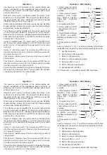
Page 8: ...sensor automatically adjusts LED brightness Operation LED Display 4 5 6 3 2 1 7 8 9 10 11 12 13 14 7 6 Operation The power on and off operation of the remote display and receiver will depend on the manufacture date and version of software in the receiver The RD15 was released with receiver software Version 5 xx Receivers with Version 5 software enable the power to be switched on or off at the RD15...

Page 9: ...sensor automatically adjusts LED brightness Operation LED Display 4 5 6 3 2 1 7 8 9 10 11 12 13 14 7 6 Operation The power on and off operation of the remote display and receiver will depend on the manufacture date and version of software in the receiver The RD15 was released with receiver software Version 5 xx Receivers with Version 5 software enable the power to be switched on or off at the RD15...

Page 10: ... Version 4 software the tilt display will always be on Fine Deadband Standard Deadband Wide Deadband 5 Cable Installation Receiver Cable Route the receiver cable from the RD15 to where the receiver is mounted Turn the receiver power off prior to connecting the receiver cable Connect the 7 socket connector to the receiver Connect the 6 pin connector to the RD15 Optional Power Cable Battery Plug the...

Page 11: ...an 2 seconds to avoid turning off The amber Offset Elevation LED will turn off confirming the return 4 Optional Swivel Mount installation Position the swivel mount in the machine s cab so the operator can easily see the LED display during machine operation Assure it does not obstruct other operator functions Determine the best mounting option for the swivel mount base Hardware is provided if a sui...

Page 12: ...t side Select Function switch four times and press the left side Set Function switch one time to set Installation Position the RD15 in the machine s cab so the operator can easily see the LED display during machine operation Assure it does not obstruct other operator functions The RD15 includes an assortmentofmountinghardwareincludingmagnets double sided tape mating Velcro strips and a rubber stra...

Page 13: ...ough fine medium and coarse The tilt display LED s will blink to indicate which deadband is selected 2 General Description The RD15 is designed to work with MCR receivers It is mounted in the cab of the machine for easy viewing by the machine operator The LED s of the RD15 display grade information similar to the LED s of the receiver Please refer to the receiver manual for specific displays and s...

Page 14: ...C to 60 C Storage Temperature 40 F to 158 F 40 C to 70 C Size 4 5 x 2 x 1 1 inch 11 4 x 5 1 x 2 8 cm Table of Contents Warranty Inside Cover General Description 2 Installation 3 Operation 6 Specifications 12 Version Chart 13 12 Operation Low Battery Display The left LED of the tilt display will blink to indicate a low battery condition The tilt display will no longer operate Replace or recharge th...

Page 15: ...orimplied and constitutes all of the manufacturer s liability with respect to merchandise sold by it 13 Software Version Operation Chart RD15 MCR Feature MCR Model Current Version 5 xx Prior Version 4 xx MCR Power On 1 2 3 Can turn on off Does not turn on off MCR Power On 1 2 Not Available Does not turn on off Disable lost beam display All Can turn on off Can not turn off Plumb mode flash to indic...

Page 16: ...ting Instructions Remote Display Model RD15 For use with MCR Laser Receivers P N ATI 010944 15 Rev B Operating Instructions Remote Display Model RD15 For use with MCR Laser Receivers P N ATI 010944 15 Rev B ...

Reviews: