2
General Description
The RD15 is designed to work with MCR receivers. It is mounted
in the cab of the machine for easy viewing by the machine
operator. The LED's of the RD15 display grade information
similar to the LED's of the receiver. Please refer to the receiver
manual for specific displays and settings.
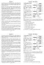
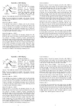
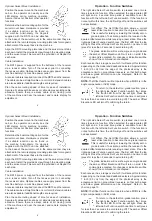
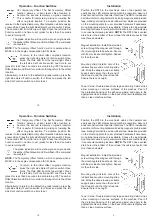
In addition to the standard grade, plumb, and tilt displays where
applicable, the RD15 provides functions to set an offset elevation
and a second temporary offset elevation on the receiver. An audio
jack is provided for earphones. Tilt indication can be displayed for
the MCR2+ and MCR3 receivers.
The RD15 power is supplied from the batteries of the receiver.
Optional cables supply power from the machine battery or a
machine power outlet.
8
9
10
1
2
2
3
3
5
6
7
4
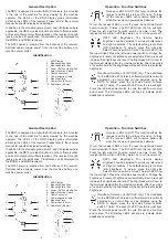
1. LED Display
2. Mounting Strap Tabs
3. Mounting Plate Tabs
4. Power / Set Function Switch
5. Select Function Switch
6. Cable Connector
7. Communication Cable
8. Mounting Plate
9. Power Jack (3.5mm)
10. Audio Jack (2.5mm)
Identification
11
Operation - Function Switches
Receiver LED's On/Off:
This function allows the
receiver's LED's to be turned off and on. Turning
off the receiver LED's will conserve battery life
when the receiver is powered by batteries.
To turn the receiver LED's on or off, press the right side Select
Function switch 5 times. The fifth LED from the top will light.
Press the left side Set Function switch one time to set. The
receiver LED's will turn off if they were on or on if they were off.
RD15 LED Brightness:
The remote display
brightness can be adjusted to suit user preferences
and light conditions. The default setting is medium
(6/8) brightness. To adjust, press the right side
Select Function switch 6 times. The sixth LED from
the top will light. Press the left side power switch to change the
brightness. 8 levels of brightness are selectable. Each press will
increase the brightness one level. The brightness will roll over to
the dimmest display after the maximum display. After 4 seconds
of no switch activity, the brightness will be set at the last selected
brightness.
Deadband Selection (for MCR2E only):
The deadband
for the MCR2E with Version 5 software (which is normally
adjusted by a control box) can be adjusted using the
RD15. To adjust, press the right side Select Function
switch 7 times. The seventh LED from the top will light.
Press the left side power switch to cycle through fine, medium
and coarse. The tilt display LED's will blink to indicate which
deadband is selected.
2
General Description
The RD15 is designed to work with MCR receivers. It is mounted
in the cab of the machine for easy viewing by the machine
operator. The LED's of the RD15 display grade information
similar to the LED's of the receiver. Please refer to the receiver
manual for specific displays and settings.
In addition to the standard grade, plumb, and tilt displays where
applicable, the RD15 provides functions to set an offset elevation
and a second temporary offset elevation on the receiver. An audio
jack is provided for earphones. Tilt indication can be displayed for
the MCR2+ and MCR3 receivers.
The RD15 power is supplied from the batteries of the receiver.
Optional cables supply power from the machine battery or a
machine power outlet.
8
9
10
1
2
2
3
3
5
6
7
4
1. LED Display
2. Mounting Strap Tabs
3. Mounting Plate Tabs
4. Power / Set Function Switch
5. Select Function Switch
6. Cable Connector
7. Communication Cable
8. Mounting Plate
9. Power Jack (3.5mm)
10. Audio Jack (2.5mm)
Identification
11
Operation - Function Switches
Receiver LED's On/Off:
This function allows the
receiver's LED's to be turned off and on. Turning
off the receiver LED's will conserve battery life
when the receiver is powered by batteries.
To turn the receiver LED's on or off, press the right side Select
Function switch 5 times. The fifth LED from the top will light.
Press the left side Set Function switch one time to set. The
receiver LED's will turn off if they were on or on if they were off.
RD15 LED Brightness:
The remote display
brightness can be adjusted to suit user preferences
and light conditions. The default setting is medium
(6/8) brightness. To adjust, press the right side
Select Function switch 6 times. The sixth LED from
the top will light. Press the left side power switch to change the
brightness. 8 levels of brightness are selectable. Each press will
increase the brightness one level. The brightness will roll over to
the dimmest display after the maximum display. After 4 seconds
of no switch activity, the brightness will be set at the last selected
brightness.
Deadband Selection (for MCR2E only):
The deadband
for the MCR2E with Version 5 software (which is normally
adjusted by a control box) can be adjusted using the
RD15. To adjust, press the right side Select Function
switch 7 times. The seventh LED from the top will light.
Press the left side power switch to cycle through fine, medium
and coarse. The tilt display LED's will blink to indicate which
deadband is selected.

