6
Operation
The power on and off operation of the remote display and
receiver will depend on the manufacture date and version of
software in the receiver. The RD15 was released with receiver
software Version 5.xx
Receivers with Version 5 software enable the power to be
switched on or off at the RD15. If the receiver has older software,
the power switch and some additional functions will operate
differently. Refer to the chart on page 13.
Older versions of software will lock the receiver keypad, disabling
keypad switches. Ensure the receiver has the desired settings
selected prior to attaching the RD15.
The software version is identified by the serial number label
on the circuit board located on the back top of the receiver.
Receivers with Version 5.xx, released approximately September
2006, allow the power switch on the RD15 to act the same as the
power switch on the receiver.
Version 5 - Battery power:
The power switch on the RD15 turns
the receiver and remote display on and off. Press the power
switch to turn on. Press and hold the power switch for 2 seconds
to turn off.
Version 5 - Machine power:
The receiver and RD15 turn on
when the machine is turned on. Press and hold the power switch
for 2 seconds to turn off.
Prior Versions - Battery power:
Power must be turned on and off
at the receiver.
Prior Versions - Machine power:
The receiver and RD15 turn on
when the machine is turned on. The connector can be removed
from the power jack to turn the power off.
Power ON will be indicated by any grade or tilt display LED when
the receiver is in the laser beam. The on-grade LED will flash
once every 4 seconds if not in a laser beam.
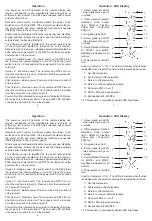
1. Above grade red LED's
- lower implement to get to
on-grade.
2. Offset elevation function
indication. Solid amber
light - Offset on. Flashing
amber light - Temporary
Offset on.
3. On-grade green LED.
4. Below grade red LED's
- raise implement to get to
on-grade.
5. Five light blade tilt display
for MCR3+ and MCR3.
Deadband indication for all
models.
6. Power switch on left side
icon.
Function Indicators (7-13)
- The LED will indicate what function
is selected when the select function switch is pressed and cycled.
7. Set offset elevation.
8. Set temporary offset elevation.
9. Return to offset elevation.
10. Return to receiver default elevation.
11. Receiver LED's on or off.
12. RD15 LED brightness selection.
13. Set deadband for MCR2E.
14. Photosensor - automatically adjusts LED brightness.
Operation - LED Display
4
5
6
3
2
1
7
8
9
10
11
12
13
14
7
6
Operation
The power on and off operation of the remote display and
receiver will depend on the manufacture date and version of
software in the receiver. The RD15 was released with receiver
software Version 5.xx
Receivers with Version 5 software enable the power to be
switched on or off at the RD15. If the receiver has older software,
the power switch and some additional functions will operate
differently. Refer to the chart on page 13.
Older versions of software will lock the receiver keypad, disabling
keypad switches. Ensure the receiver has the desired settings
selected prior to attaching the RD15.
The software version is identified by the serial number label
on the circuit board located on the back top of the receiver.
Receivers with Version 5.xx, released approximately September
2006, allow the power switch on the RD15 to act the same as the
power switch on the receiver.
Version 5 - Battery power:
The power switch on the RD15 turns
the receiver and remote display on and off. Press the power
switch to turn on. Press and hold the power switch for 2 seconds
to turn off.
Version 5 - Machine power:
The receiver and RD15 turn on
when the machine is turned on. Press and hold the power switch
for 2 seconds to turn off.
Prior Versions - Battery power:
Power must be turned on and off
at the receiver.
Prior Versions - Machine power:
The receiver and RD15 turn on
when the machine is turned on. The connector can be removed
from the power jack to turn the power off.
Power ON will be indicated by any grade or tilt display LED when
the receiver is in the laser beam. The on-grade LED will flash
once every 4 seconds if not in a laser beam.
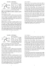
1. Above grade red LED's
- lower implement to get to
on-grade.
2. Offset elevation function
indication. Solid amber
light - Offset on. Flashing
amber light - Temporary
Offset on.
3. On-grade green LED.
4. Below grade red LED's
- raise implement to get to
on-grade.
5. Five light blade tilt display
for MCR3+ and MCR3.
Deadband indication for all
models.
6. Power switch on left side
icon.
Function Indicators (7-13)
- The LED will indicate what function
is selected when the select function switch is pressed and cycled.
7. Set offset elevation.
8. Set temporary offset elevation.
9. Return to offset elevation.
10. Return to receiver default elevation.
11. Receiver LED's on or off.
12. RD15 LED brightness selection.
13. Set deadband for MCR2E.
14. Photosensor - automatically adjusts LED brightness.
Operation - LED Display
4
5
6
3
2
1
7
8
9
10
11
12
13
14
7

