12
FuturaSun srl – The specifications in this manual are subject to revisions without further notice
This document applies to the module series FU XXX M ZEBRA
9b) How to Manage the Packaging
Each package has been designed to allow the
shipment and storage of modules in order to
maintain their integrity unchanged over time,
provided that the information and indications
supplied by FUTURASUN are closely
observed and followed. These indications are
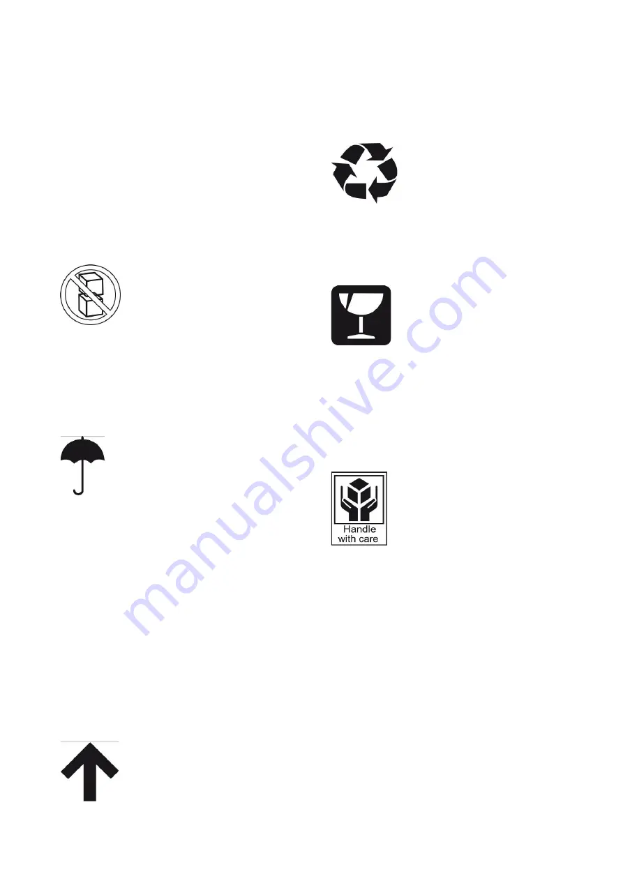
summarised by a series of standard symbols
posted in a visible manner on each pallet. The
list below illustrates the meaning of each
symbol (you can find some of them in each
pallet):
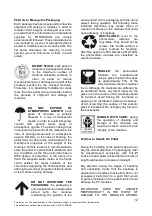
DO NOT STACK:
each pallet of
modules is packaged according
to the maximum number of
modules stackable vertically, in
order to avoid or reduce
mechanical stress or damage as a result of the
pressure exerted by the stacked modules.
Therefore, it is absolutely forbidden to stack
more than one pallet on top of another, both in
the process of shipment and storage of
modules.
DO
NOT
EXPOSE
TO
ATMOSPHERIC AGENTS:
each
pallet of modules is suitably
dressed in a cap of transparent
plastic in order to avoid temporary
contact with generic water spray or
atmospheric agents. The plastic casing does
not ensure the protection of the modules in the
case of prolonged exposure to atmospheric
agents. Similarly, in the case of flooding, the
pallet does not ensure the maintenance of the
mechanical properties of the weight of the
modules. For this reason it is recommended to
store the pallet in a place that is sheltered and
dry. In addition, as the the junction box has an
IP68 degree of protection, in the event of a
flood the stagnant water inside of the frame
could oxidise the metal contacts of the
connectors degrading the characteristics and
altering the electrical properties of the contacts
of the module causing damage.
DO NOT OVERTURN THE
PACKAGING:
the packaging is
only designed to be handled and
stored
with
the
modules
maintaining the position of the
arrow printed on the packaging, with the arrow
always facing upwards. Not following these
indicated directions may create forms of
mechanical stress on the modules that could
cause damage or breakage.
RECYCLABLE:
most of the
photovoltaic
modules
are
recyclable. They should not be
thrown into landfill without a
proper method for recycling.
Aftert the approval of EU Directive 2012/19/Ue
the photovoltaic modules are classified as
electronic waste.
FRAGILE:
the photovoltaic
modules
are
manufactured
using a glass front which makes
up approximately 70% of the
total materials used to construct
them. Although the modules are stiffened by
an aluminium frame, any direct impact to the
glass or on the corners of the modules should
be avoided. Avoid flexing the laminates or
applying non distributed loads and
stresses.
Avoid scratching the surface of the
exterior
glass or backsheet. Do not apply any forces to
the backsheets.
HANDLE WITH CARE:
during
the operation of shipping and
storage of the modules use
maximum care to ensure the full
integrity of the modules.
9c) How to Handle the Pallet
During the handling of the pallet make sure to
pay the utmost attention. The packaging must
be raised/moved exclusively with fork-lift
trucks or hand pallet trucks fitted with forks of
length appropriate to its size and weight.
Pay attention during the stages of handling
and unpacking. Verify that the package is
positioned on a surface that is either flat or not
excessively deformed to a point that would
impart an inclination to the pallets which could
damage the PV modules.
FUTURASUN
DOES
NOT
ASSUME
RESPONSIBILITY IN THE EVENT OF
DAMAGE TO THE MODULES ARISING


