background image

FuturaSun srl – The specifications in this manual are subject to revisions without further notice 
This document applies to the module series FU XXX M ZEBRA 

1. General Information 

The  photovoltaic  (PV)  modules  FU  XXX  M 
ZEBRA,  (hereafter  “FU  XXX”  or  “FU”)  are 
devices  that  produce  electrical  energy  by 
converting  the  sunlight’s  radiation  reaching 
their  surface,  when  appropriately  exposed, 
into continuous/direct current (DC). 
 
The  FU  modules  are  intended  to  be  used  in 
photovoltaic module systems connected to the 
electrical grid. It is also possible to use them in 
battery powered photovoltaic module systems 
(stand-alone). 
 
The  rated  currents  at  Standard  Test 
Conditions  (STC)  of  the  FU  modules  are 
variable  depending  on  the  model  and  the 
relative  power  rating,  as  indicated  in  the 
respective 

technical data sheets.

 Most of the 

electrical parameters of the modules, specified 
in  the  datasheets,  are  determinable  only  by 
using special instrumentation in the laboratory; 
therefore, only some of them are measurable 
outside 

of 

lab, 

using 

common 

instrumentation 

(voltmeter, 

AM 

meter, 

solarimeter/pyranometer). 

 
It  is  possible,  following  very  precise 
procedures, 

to 

carry 

out 

electrical 

measurements  of  voltage  and  current  as 
snapshots,  which  enable  you  to  monitor  the 
operation  of  the  modules  and  determine 
possible, although rare, anomalies. 
 
The  electrical  output  parameters  for  FU 
modules,  of  technical  importance  during  the 
operation,  installation  and  maintenance,  are 
the following: 
 

  Voltage  at  open  circuit  (V

oc

)  with 

tolerance of ± 4% 

  Current  at  short  circuit  (I

sc

)  with 

tolerance of ± 5% 

  Voltage  at  point  of  maximum  power 

(Vmpp) 

  Current  at  point  of  maximum  power 

(Impp) 

  Power (P

max)

 with tolerance of ± 3% 

  Solar radiation in W/m

2

 at the time 

  Temperature of the modules  

 
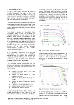
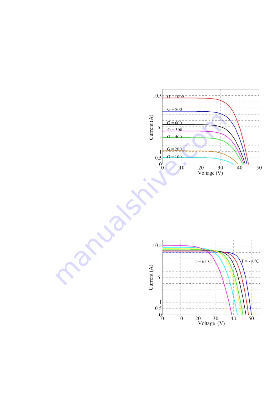
The  general  performance  of  the  modules  is 
heavily  dependent  on  the  intensity  of  the 
incident solar radiation, as illustrated in Fig.1. 

Acheiving  maximum  performance  requires 
proper installation, with the modules oriented 
towards the South in nothern hemisphere and 
their  surface  exposed  as  perpendicularly  as 
possible  to  the  incident  rays  of  the  sun; 
furthermore, avoiding any shading caused by 
obstacles  in  and  around  the  area  of 
installation.  


Fig. 1:


IV curve at different irradiance 

 
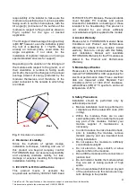
A high ambient temperature and therefore, an 
increased  operational  temperature  of  the 
modules,  also  contribute  to  a  proportional 
reduction  in  electrical  performance.  Please 
see fig. 2 


Fig. 2:


IV curve at different temperatures


In order to optimize the production of electrical 
energy  of  the  modules,  and  therefore  of  the 
system connected to an electrical grid, it is the 

Summary of Contents for FU M ZEBRA Series

Page 1: ...Author FuturaSun Document name Installation_manual_FuturaSun_2020 Revision date 01 09 2020 SAFETY AND INSTALLATION MANUAL Photovoltaic Modules FU XXX M ZEBRA...

Page 2: ...cument applies to the module series FU XXX M ZEBRA CONTENTS 1 General Information 3 2 Disclaimer of Liability 4 3 IEC 61215 61730 certifications 4 4 Limited Warranty 4 5 Module Specification 4 6 Safet...

Page 3: ...current as snapshots which enable you to monitor the operation of the modules and determine possible although rare anomalies The electrical output parameters for FU modules of technical importance dur...

Page 4: ...dards cover flat plate PV modules and panels intended for installation on buildings or those intended to be freestanding This product is not intended for use where artificially concentrated sunlight i...

Page 5: ...constitute an increased risk of electric shock and may cause injury or death Modules shall not be connected in series to create strings with a higher voltage than the maximum system design voltage and...

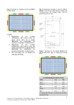
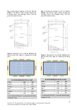
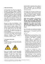
Page 6: ...load and 2400 Pascal 3600 including a safety factor of 1 5 wind load when the module is fixed in the green area See Fig 4 and following The FU XXX M ZEBRA modules regardless of half cut cell configur...

Page 7: ...ion with half cut cells the yellow areas allow for a typical load of 2400 1600 Pa 3600 2400 Pa maximum including 1 5 safety factor The red areas are not allowed for clamping and fixing Fig 5 Mechanica...

Page 8: ...ZEBRA 132 half cut cells Color min max Green 1 355 555 Yellow 1 0 728 Red 1 728 1092 Yellow 2 0 149 Red 2 149 847 1 on long side of frame 2 on short side of frame tolerance 2 mm Fig 7 Mechanical drawi...

Page 9: ...main power supply may only be performed by authorized and qualified persons Before connection of the system to the grid the PV system must be approved for correct installation by an electrician respon...

Page 10: ...the Voc and Isc When the PV modules are instead connected in series parallel configuration to an inverter from its display it is possible to read Operational voltage at maximum power output Vmpp of th...

Page 11: ...rves to identify anomalies The maximum module configuration when connected in series is 21 modules size 120 half cut cells for 1000 V DC systems The maximum module configuration when connected in seri...

Page 12: ...he connectors degrading the characteristics and altering the electrical properties of the contacts of the module causing damage DO NOT OVERTURN THE PACKAGING the packaging is only designed to be handl...

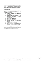
Page 13: ...following procedures for the unpacking of modules Place the packaging on a stable and flat surface Using a cutter cut the plastic wrap surrounding the package or to open the paper box Remove the plas...

Reviews: