7
FuturaSun srl – The specifications in this manual are subject to revisions without further notice
This document applies to the module series FU XXX M ZEBRA
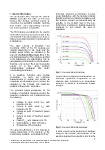
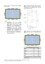
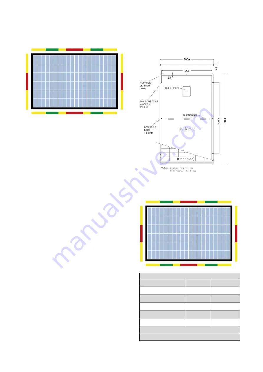
Fig. 4:
Positions for clamping and fixing (ZEBRA
module series)
Legend:
•
Regardless
of
the
module
configuration with half-cut cells, the
green areas allow for a typical
3600/2400
Pa
(5400/3600
Pa
maximum including 1.5 safety factor).
•
Regardless
of
the
module
configuration with half-cut cells, the
yellow areas allow for a typical load of
2400/1600
Pa
(3600/2400
Pa
maximum including 1.5 safety factor).
•
The red areas are not allowed for
clamping and fixing.
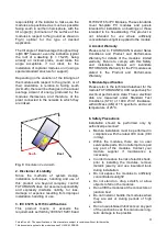
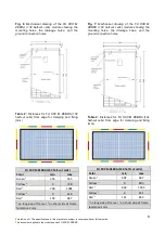
Fig. 5:
Mechanical drawing of the FU XXX M
ZEBRA (120 half-cut cells) module showing the
mounting holes, the drainage holes, and the
ground connection holes.
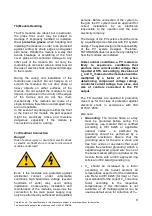
Table 1:
Distances for FU XXX M ZEBRA (120
half-cut cells) from edge for clamping and fixing
(mm)
FU XXX M ZEBRA (120 half-cut cells)
Color
min
max
Green
1
321
521
Yellow
1
0
674
Red
1
674
1011
Yellow
2
0
151
Red
2
151
853
1
on long side of frame |
2
on short side of frame
tolerance 2 mm


