8
FuturaSun srl – The specifications in this manual are subject to revisions without further notice
This document applies to the module series FU XXX M ZEBRA
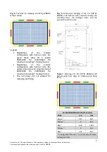
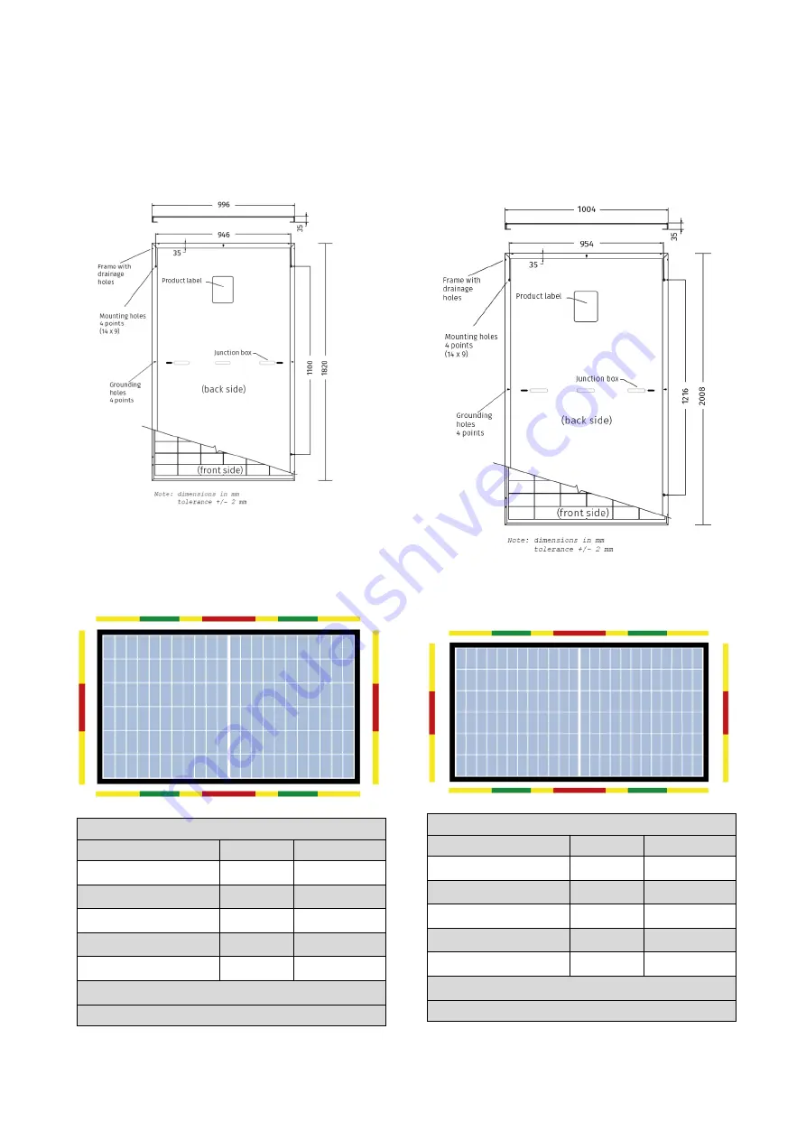
Fig. 6:
Mechanical drawing of the FU XXX M
ZEBRA (132 half-cut cells) module showing the
mounting holes, the drainage holes, and the
ground connection holes.
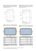
Table 2:
Distances for FU XXX M ZEBRA (132
half-cut cells) from edge for clamping and fixing
(mm)
FU XXX M ZEBRA (132 half-cut cells)
Color
min
max
Green
1
355
555
Yellow
1
0
728
Red
1
728
1092
Yellow
2
0
149
Red
2
149
847
1
on long side of frame |
2
on short side of frame
tolerance 2 mm
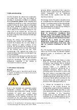
Fig. 7:
Mechanical drawing of the FU XXX M
ZEBRA (144 half-cut cells) module showing the
mounting holes, the drainage holes, and the
ground connection holes.
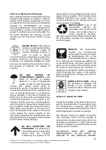
Table 2:
Distances for FU XXX M ZEBRA (144
half-cut cells) from edge for clamping and fixing
(mm)
FU XXX M ZEBRA (144 half-cut cells)
Color
min
max
Green
1
402
602
Yellow
1
0
803
Red
1
803
1205
Yellow
2
0
151
Red
2
151
853
1
on long side of frame |
2
on short side of frame
tolerance 2 mm


