background image

Summary of Contents for TMC-8S0M

Page 1: ...DOMAIN TMC 8S0M lUser s Guide a Bit High Performance SCSI Host Adapters ...

Page 2: ......

Page 3: ...n This manual copyrighted with All Rights Reserved Under the copyright laws this manual may not be copied in whole or in part without written permission from Future Domain except for normal use by the original buyer s This exception does not allow copies to be made for sale to others Under the law copying includes translating into another language or format For written permission contact Future Do...

Page 4: ......

Page 5: ...sed during the type test therefore properly shielded and terminated data cables should be used to reduce potential interference However there is no guarantee that interference will not occur in a particular installation If this equipment does cause interference to radio and television reception which can be determined by turning the equipment off and on the user is encouraged to try to correct the...

Page 6: ......

Page 7: ... Future Domain s Small Computer Systems Interface SCSI TMC 850M host adapter are as follows IBM PC XT AT or compatible computer SCSI device s such as hard disk WORM optical disk CD ROM player tape drive or other SCSI peripherals PC DOS or MS DOS version 3 x or greater The following operating systems are also supported for the TMC 850M INTERACfIVE UNIX 386 ix V1 0 6 and V2 x SCO XENIX operating sys...

Page 8: ...and list of features of the TMC 850M Chapter 2 CONFIGURATION discusses factory settings and has a Quick Reference Guide Chapter 3 INSTALLATION contains instructions on how to install the TMC 850M in your computer Chapter 4 TECHNICAL REFERENCE includes sections on SCSI BIOS jumper settings connector pinouts and termination Chapter 5 TROUBLESHOOTING includes information about Diagnostic and Error Me...

Page 9: ...ains additional information specific to Section 4 1 4 Special Sector Size Handling Future Domain s TMC 950 Technical Reference Manual model number FDC 950T Future Domain documentation may be purchased by contacting your nearest authorized dealer or distributor Electromagnetics John D Kraus Keith R Carver McGraw Hill 1973 Chapter 13 may be used as a reference to Section 4 6 Termination PREFACE iii ...

Page 10: ...TMC 850M User s Guide 10 15 91 iv PREFACE ...

Page 11: ...s 3 6 3 6 Tape and CD ROM Drives 3 6 3 7 Configuring for IBM AT and Compatibles 3 6 4 0 TECHNICAL REFERENCE 4 1 4 1 SCSI BIOS 4 1 4 1 1 General Description 4 1 4 1 2 Addressing Conventions 4 2 4 1 3 Boot Sequence 4 3 4 1 4 Special Sector Size Handling 4 4 4 2 Address Jumpers 4 4 4 3 Interrupts 4 6 4 4 External SCSI Connector 4 7 4 5 Internal SCSI Connector 4 8 4 6 Termination 4 9 4 7 Summary of Co...

Page 12: ...TMC 850M User s Guide 10 15 91 vi CONTENTS ...

Page 13: ...BIOS automatically adjusts for use in the system The SCSI host adapter uses no DMA channels no I O ports and no interrupts under PC MS DOS All operations are memory mapped The standard configuration uses 8K of memory space at address CAOOO in the system the area reserved for ROM BIOS 1 1 TMC 850M Features Future Domain SCSI BIOS supports a maximum oftwo SCSI disk drives Additional devices require ...

Page 14: ...TMC 850M User s Guide 10 15 91 NOTES 1 2 INTRODUCTION ...

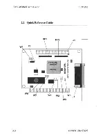
Page 15: ...2 OPEN W3 1 3 2 4 OPEN Interrupts used None under DOS jumper set for interrupt 5 W7 I O Ports used None e The SCSI BIOS supports up to two hard disk drives Other devices require a separate driver If the factory configuration meets your requirements proceed to Chapter 3 INSTALLATION If you need to modify the configuration of the TMC 850M read Chapter 4 TECHNICAL REFERENCE CONFIGURATION 2 1 ...

Page 16: ...TMC 850M User s Guide 10 15 91 22 Quick Reference Guide RP1 R J2 o W3 2 2 CONFIGURATION ...

Page 17: ...TION POWER ENABLED TERMINATION POWER DISABLED ZERO WAIT STATE ENABLED ZERO WAIT STATE DISABLED IRQ3 IRQS TMC 850M ADDRESS JUMPER SETllNGS JUMPER SETllNGS W1 W2 W3 0 0 1 2 3 4 0 1 1 2 3 4 1 0 1 2 3 4 1 1 1 2 3 4 0 0 1 3 2 4 1 0 1 3 2 4 NOTE 1 SHORTED O OPEN CONFIGURATION MEMORY FUNCll0NS RANGE CAOOh CSOOh PRIMARY ADDRESS CEOOh RANGES DEOOh ESOOh EXTENDED RANGE ECOOh EXTENDED RANGE 2 3 ...

Page 18: ...1 2 4 UNIX XENIX and Novell operating system drivers utilize hardware interrupts When interrupts are used under these operating systems be sure the device driver specifies the same interrupt line jumpered on the board CONFIGURATION ...

Page 19: ...ion instructions for the particular disk or tape drive Step 2 Place the system unit switch to the OFF position Step 3 Tum OFF all external equipment Step 4 Remove the system unit cover by fonowing the instructions provided with the system For IBM PC AT systems use the screwdriver to remove the screws at the rear of the system cabinet and slide the unit cover forward and off See diagram below INSTA...

Page 20: ...xternal Installation if using an external cabinet Step 1 2 1 Locate the 50 pin SCSI ribbon cable and install one end on the 50 pin SCSI header J2 on the TMC 850M The red or blue stripe on the cable should be aligned with the side of the header labeled 1 See the figure below 50 49 50 Pin Header J2 Step 2 Align the TMC 850M board with an 8 or 16 bit expansion slot and firmly plug it in Reinstall the...

Page 21: ...s not conflict with any of the disk drive addresses assigned in step 3 SCSI address 6 may not be assigned to the tape as this address is reserved for the host adapter See your tape drive installation manual for details on setting the SCSI address If no disk drives are being used and the TMC 850M is only being used to control tape CD ROM or optical drives you may remove the BIOS ROM chip to speed u...

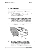
Page 22: ...20 or equivalent into the 25 pin connector at the rear of the 1MC 850M board Secure the cable to the TMC 850M using the thumbscrews on the cable Step 3 Connect the other end of the cable to the connector of the external SCSI device as shown below Host Adapter Connector Cable Only the last device in the external box should be terminated Refer to Section 4 6 Termination and to your drive manufacture...

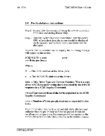
Page 23: ...es per Sector Where www N The SCSI address of the drive 0 5 n The SCSI LUN address of the device xxxx Disk Drive Type and Version Number This is a copy of the ASCII character string that is returned by the drive in response to a SCSI Inquiry Command www Firmware revision of the device reported in the SCSI Inquiry Command yyyy Number of bytes per physical sector reported by the drive This prompt id...

Page 24: ...se refer to the optical drive s installation manual for more information 3 6 Tape or CD ROM Drives When installing a tape or CD ROM drive assign it to a unique SCSI address which does not conflict with any of the disk drive addresses assigned in step 3 SCSI address 6 may not be assigned to the tape or CD ROM as this address is reserved for the host adapter See your tape or CD ROM drive installatio...

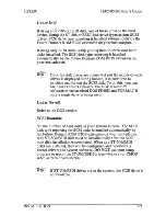
Page 25: ...t the SCSI disk To do this you can use either Future Domain s The Disk Maestro software or the standard DOS FDISK and FORMAT if only a single drive is being used Under Novell Refer to the DOS section SCSI Bootable Set the number of hard disks in your system to zero The SCSI disk type reporting for SCSI disks is handled automatically by the Future Domain ROM BIOS extension on your host adapter Any ...

Page 26: ...r system to show the ST 506 and ESDI drives as detailed in your manufacturer s instructions DO NOT report any SCSI disks in your setup Disk type reporting for SCSI disks is handled automatically by Future Domain s ROM BIOS extensions on your host adapter INSTALLATION ...

Page 27: ...mpatible with the IBM PC AT adapter ROM BIOS interface specifications and utilizes the standard Interrupt 13 mass storage vector It contains the capability to allow booting from devices that can be made IBM media compatible In addition to the basic set of commands extensions are available to provide direct control of SCSI devices for the purposes of control identification formatting extended addre...

Page 28: ...ws addressing of LUNs other than 0 must be setup at SCSI 10 4 or 5 Ifa device does not properly return an error code when the incorrect LUN is addressed it cannot be set at SCSI ID 4 or 5 The symptom of this error is that the same drive name will appear multiple times on the screen during bootup When installing a tape or CD ROM drive assign it to a unique SCSI address which does not conflict with ...

Page 29: ...nterrogated Step 3 If a drive responds to the Test Unit Ready command whether it is ready or not the drive is sent an Inquiry command to read out the drive description This is displayed on the screen along with the drive s SCSI address and LUN number Step 4 The SCSI bus was checked for a parity error during the issuing of the Test Unit Ready command If the adapter detected a parity error further c...

Page 30: ...he system should be assigned to the lower SCSI addresses while optical media should be assigned to an upper SCSI address i e SCSI address 5 This allows booting from the magnetic media whereas a device with a non standard sector size will not be allowed to boot Future Domain s OEM Toolkit Developer s Manual contains additional detailed information See Additional Documentation located in the PREFACE...

Page 31: ...change the TMC 850M s board address use the jumpers to set the address to one of the three other possible adapter addresses shown below Me 850M ADDRESS JUMPER SETI lNGS JUMPER SETIU GS W1 W2 W3 0 0 1 2 3 4 I 1 1 2 3 4 1 I 1 2 3 4 1 1 1 2 3 4 0 I 1 3 2 4 1 0 1 3 2 4 NOTE 1 SHORTED O OPEN MEMORY FUNCTIONS RANGE CAOOh CSOOh PRIMARY ADDRESS CEOOh RANGES DEOOh ESOOh EXTENDED RANGE ECOOh EXTENDED RANGE ...

Page 32: ...nterrupt line as is jumpered on the board The UNIX XENIX and Novell drivers need to be setup for the interrupt you have chosen The TMC 850M is shipped with the jumper set for interrupt 5 The jumper from W6 to the center post selects IRQ3 The jumper from W7 to the center post selects IRQ5 see illustration below IRQ3 W6 1 1 1 W7 _ _ _ _ J IRQS W6 1 1 1 W7 _ _ _ _ J Factory Default For easy future re...

Page 33: ... 25 pin D to 50 pin Amphenol SCSI external standard cable This cable may be used to connect the TMC 850M directly to enclosures with the SCSI standard external connectof You may order this cable Future Domain model HCA 120 from your dealer Of distributor The pinouts of the 25 pin connector are as follows PIN SIGNAL PIN SIGNAL 1 REQ 14 GROUND 2 MSG 15 C D 3 I O 16 GROUND 4 RST 17 ATN 5 ACK 18 GROUN...

Page 34: ... 5 GND 6 SCZ 7 GND 8 SC3 9 GND 10 SC4 11 GND 12 SCS 13 GND 14 SC6 15 GND 16 SC7 17 GND 18 SPAR 19 GND 20 GND 21 GND 22 GND 23 GND 24 GND 25 not used 26 TERMPOWER 27 GND 28 GND 29 GND 30 GND 31 GND 32 SA1N 33 GND 34 GND 35 GND 36 SBSY 37 GND 38 SACK 39 GND 40 SRST 41 GND 42 SMSG 43 GND 44 SSEL 45 GND 46 SCD 47 GND 48 SREQ 49 GND 50 SIO 4 8 TECHNICAL REFERENCE ...

Page 35: ...owed to ensure proper operation ofthe SCSI bus host adapters and peripherals Two terminations must be present on the bus More than two terminations may damage the host adapter or peripherals The end device on either side total of two of the SCSI bus must have the terminators When installing terminator resistor packs be sure to orient Pin 1 dot on resistor pack indicates pin 1 af the resistor pack ...

Page 36: ...W4 If the host adapter is not at the end of the SCSI bus remove the termination resistors RP1 and RP2 Make sure the terminators are in place on the devices at the end of the SCSI bus The following is a technical discussion of termination and cabling Most users need not read this section The SCSI standard defines the following termination scheme 5V 5V 220 220 7438 330 330 Ground 5V Voltage Regulato...

Page 37: ...tches due to multiple taps to the transmission line in the form of devices Clustering loads at the end of the cable see diagram below creates an impedance mismatch NOT RECOMMENDED To avoid this problem group all loads evenly across the cable spaced at least 03 meters apart Keep the tap lengths as short as possible The SCSI Spec ANSI X3 131 1986 requires a stub length less than 1 meter see diagram ...

Page 38: ...Cabling problems should be addressed by a qualified electrical engineer For more information see Additional Documentation located in the PREFACE 4 7 Summary of Controller Optio s RP1 J2 o W3 TMC 850M SCSI Host Adapter TECHNICAL REFERENCE ...

Page 39: ...AddreSsing Configuration Termination Power Zero Wait State Selectable IRQs 3 or 5 Thermal Fuse Active Termination Resistor Packs External SCSI Port 25 Pin Apple Type Internal SCSI Port 50 Pin Connector J1 is a 25 pin Apple signal type connector to be used in conjunction with the Future Domain HCA 120 or compatible type cable TECHNICAL REFERENCE 4 13 ...

Page 40: ...TMC 850M User s Guide 10 15 91 NOTES 4 14 TECHNICAL REFERENCE ...

Page 41: ... is powered on or is rebooted Diagnostics include the following Checksum test of the ROM BIOS Loopback test of the Basic SCSI data path test cable and connector Internal Chip RAM test A failure of anyone of these tests will cause an error message to be displayed These error messages are Adapter SelfTestfailed Adapter RAMfailure No SCSI drives found Check cables andpower Error in Read Capacity Comm...

Page 42: ...rs and try all alternate addresses Problem 2 The Future Domain BIOS banner does not appear on screen after a several minutes or during boot process and I cannot access the drive s The message Adapter Ram Test Failure is displayed a Check to see if the card is properly seated in the computer b A conflict in addressing is possible see Section 4 2 Address Jumpers and try all alternate addresses c On ...

Page 43: ...manufacturer or dealer f Check for proper bus termination and termination power Problem 4 The message Adapter SelfTest Failed is displayed What does this indicate a This usually indicates the loopback test on the SCSI bus failed which means the 50 pin cable is installed backwards on one of the SCSI devices Carefully check the SCSI connection of each device and verify that Pin l on the connector is...

Page 44: ... termination and termination power d Replace the hard disk and try again e Check with the hard disk drive manufacturer or dealer to ensure that it supports the Common Command Set Problem 6 The message Fatal Disk Error appears What should I check a This message indicates that during the setup the SCSI drives were counted into your total amount of hard disks installed b Re run your system setup prog...

Page 45: ...ned the same algorithm is used to translate from a head sector cylinder location to a Logical Block Address which is used by the SCSI drive The algorithm used by Future Domain host adapters switches between 17 34 or 63 sectors track depending on the capacity of the drive being used The values returned by the ROM BIOS are Sectorsrrrack 17 34 63 adjusted based on capacity Number of Heads variable ad...

Page 46: ...TMC 850M User s Guide 10 15 91 NOTES ...

Page 47: ......

Page 48: ... DOMAIN 2801 McGaw Avenue Irvine California 92714 PH 714 253 0400 FAX 714 253 0913 P N 55 00850 030 00 FDe 850M I ...

Reviews: