


12
•
EN
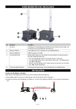
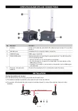
OPERATING ELEMENTS AND CONNECTIONS
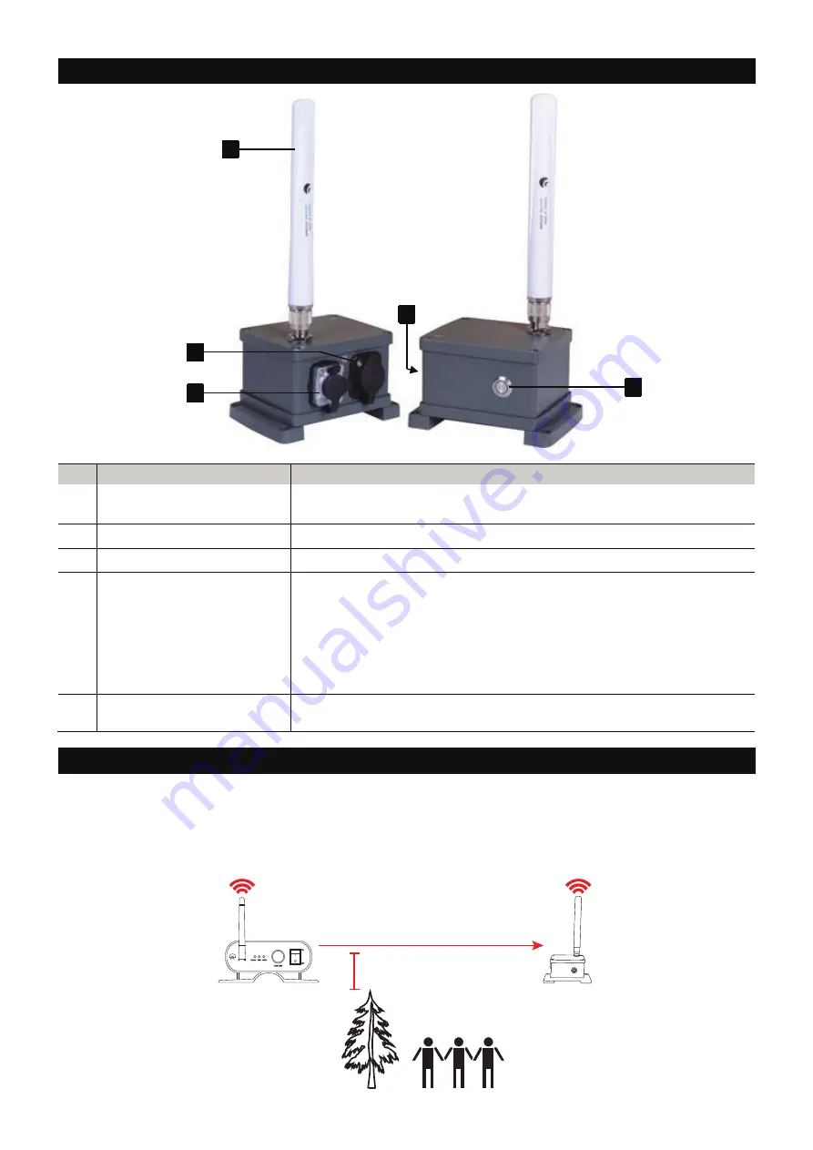
No. Element
Function
1
Antenna
Screw on the antenna provided to the antenna input and put it in a vertical
position.
2
AC230V jack
Lockable IP T-Con input for mains connection
3
DMX OUT plug
DMX output, 3-pin XLR
4
FUNCTION button
Illuminated button for switching the operating mode. The LED shows the
current operating status:
• Off: The receiver is not connected to a transmitter
• On: The receiver is connected to a transmitter, the transmission of the
DMX data is running
• Flashing: The receiver is connected to a transmitter, but no DMX signal
is transmitted
5
Pressure compensation
element
Prevents the development of condensation inside the device.
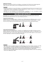
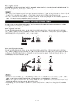
INSTALLATION
Placing transmitter and receiver
For successful linking, the following requirements should be met:
1) The distance between transmitter and receiver should not exceed 500 m.
2) The position of the transmitter and receiver should be at least 1 m above the audience, trees and other
obstacles.
1
3
2
4
5
Receiver
Transmitter
min. 1m
max.
in line-of-sight
500m
Summary of Contents for WDR-G5 RX IP
Page 8: ...8 DE ...
Page 15: ...15 EN ...