background image

ARMS 


COM AQUA TL UM REV. 02 

20 

AQUA TL 

7


Arms 

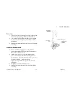
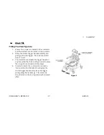
Adjusting The Arms Figure 3Figure 4


WARNING 

After 

ANY

 adjustments, repair or service and 

BEFORE

 use, 

make sure all attaching hardware is tightened securely – 
otherwise injury or damage may occur


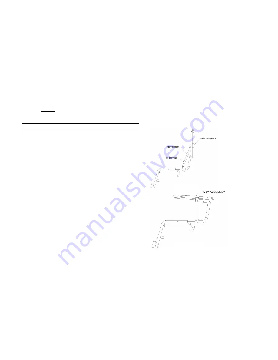
Rotating Arm Assembly Upwards\Downwards 


1.


Grasp the top portion of the arm assembly and 
rotate the arm upwards to the position shown in 
the figure in lower right corner.   One should 
notice the arm outer tube sliding along the arm 
inner tube in order to achieve a large rotation 
angle and help to support the armrest while it is 
resting vertically. 

2.


At this point the arm assembly should come to a 
stop.  The occupant can be transferred to another 
device such as a wheelchair or bed. 


3. 

In order to bring the arm assembly down to the 
‘normal’ position grasp the top portion of the arm 
assembly and rotate the arm downwards to the 
position shown in the lower left corner until the 
arm comes to a stop.


FIGURE 1 

FIGURE 2 

Summary of Contents for Aqua TL

Page 1: ...USER MANUAL Aqua TL ...

Page 2: ...ual before using this wheelchair Thank you for choosing Future Mobility Healthcare Inc If you have any questions please do not hesitate to write or call us at the address and telephone number below Future Mobility Healthcare Inc Customer Service Canada 6750 Professional Court Mississauga ON L4V 1X6 Phone 888 737 4011 or 905 671 1661 Fax 905 671 3377 e mail orderdesk futuremobility ca www futuremob...

Page 3: ...K CANES 11 FASTENERS 11 FOOTRESTS 12 POSITIONING BELTS 12 QUICK RELEASE AXLES 12 REAR WHEEL AXLES 13 REAR WHEEL LOCKS 13 FEATURES 14 SAFETY INSPECTION CHECKLIST 15 TROUBLESHOOTING 16 LABELS 17 6 FRONT RIGGINGS 18 INSTALLING AND ADJUSTING THE FRONT RIGGING FIGURE 1 FIGURE 218 7 ARMS 20 ADJUSTING THE ARMS FIGURE 3FIGURE 4 20 8 BACK 21 REPLACING BACK UPHOLSTERY FIGURE 5 21 9 SEATING 22 REPLACING SEAT...

Page 4: ...COM AQUA TL UM REV 02 4 AQUA TL 16 WARRANTY 32 LIFETIME 32 FOR TWO 2 YEARS 32 FOR 90 DAYS 32 LIMITATIONS 33 WARRANTY PROCEDURES 33 ...

Page 5: ... such things as 1 The level of your disability strength balance and coordination 2 The places and terrain that you are likely to use your chair 3 The need for options for your safety and comfort such as anti tip tubes positioning belts or special seating systems REVIEW THIS MANUAL OFTEN Before using this chair you and each person who may assist you should read this entire manual and make sure to f...

Page 6: ...nd cause severe injury to the rider or others TO REDUCE THE RISK WARNING 1 BEFORE riding you should be trained in the safe use of this chair by your health care advisor 2 Practice bending reaching and transfers until you know the limit of your ability Have someone help you until you know what can cause a fall or tip over and how to avoid doing so 3 Be aware that you must develop your own methods f...

Page 7: ...r chair CENTER OF GRAVITY WARNING The point where this chair will tip forward back or to the side depends on its center of gravity and stability How your chair is set up the options you select and the changes you make may affect the risk of a fall or tip over 1 The Most Important Adjustments Are a The position of the rear wheels The more you move the rear wheels forward the more likely your chair ...

Page 8: ...ed in place 5 DO NOT reach or lean over the top of the seat back This may damage one or both backrest tubes and cause you to fall 6 If You Must Reach Or Lean a Do not lock the rear wheels This creates a tip point and makes a fall or tip over more likely b Do not put pressure on the footrests c Move your chair as close as you can to the object you wish to reach RAMPS AND SLOPES WARNING Riding on a ...

Page 9: ... board 5 Rotate the front casters until they are as far forward as possible 6 If you can remove or swing footrests out of the way a Make sure your feet do not catch in the space between the footrests Avoid putting weight on the footrests as this may cause the chair to tip 4 ATTENDANT WARNINGS TILTING THE WHEELCHAIR WARNING In preparation to operate the tilt 1 Always verify that the arms of the rid...

Page 10: ...nd tilt the chair up on the rear wheels so that the front casters clear the curb or step 3 Move forward placing the front casters on the upper level as soon as you are sure they are past the edge 4 Continue forward until the rear wheels contact the face of the curb or step Lift and roll the rear wheels to the upper level DESCENDING STAIRS WARNING 1 Use at least two attendants to move a chair and r...

Page 11: ...our chair may tip over 3 Keep Anti Tip Tubes Locked In Place UNLESS a You have an attendant or b You have to climb or descend a curb or overcome an obstacle and can safely do so without them At these times make sure anti tip tubes are up out of the way ARMRESTS WARNING Armrests will not bear the weight of this chair 1 NEVER lift this chair by its armrests They may come loose or break 2 Lift this c...

Page 12: ... suffocate due to pressure from the belts 3 The belts must be snug but must not be so tight that they interfere with breathing You should be able to slide your open hand flat between the belt and the rider 4 A pelvic wedge or a similar device can help keep the rider from sliding down in the seat Consult with the rider s doctor nurse or therapist to find out if the rider needs such a device 5 Use p...

Page 13: ...e sure wheel locks are embedded in tires at least 1 8 inch when locked REAR WHEEL LOCKS WARNING Rear wheel locks are NOT designed to slow or stop a moving wheelchair Use them only to keep the rear wheels from rolling when your chair is at a complete stop 1 NEVER use rear wheel locks to try to slow or stop your chair when it is moving Doing so may cause you to veer out of control 2 To keep the rear...

Page 14: ...ro polish Seat Width 14 17 20 22 Overall Width Seat Width 4 Seat to Floor 20 21 1 2 Caster Size 5 Urethane with lock Back Style Foam Skinned back on 17 seat width only or mesh back with tension adjustment Back Height Low back 17 or High Back 20 Arm Style Full Length fixed height flip up gel Front Riggings Swing away leg rests Weight Capacity 250lbs 114kg on 14 17 20 350lbs 159kg on 22 wide Heavy D...

Page 15: ...ent frame or cross tubes X X X X CASTER LOCKS Caster locks easy to engage Caster locks prevent chair from moving when engaged X X X X SEAT AND BACK Inspect for rips or sagging Inspect for loose or broken hardware Inspect cane for wear looseness X X X X X X FRONT CASTERS FORKS Inspect caster fork assembly for proper tension by spinning caster caster should come to a gradual stop Adjust bearing syst...

Page 16: ...y deformation corrosion breakage Check all fasteners on a regular basic to ensure that all connections remain secure Troubleshooting Chair Veers Right Left Sluggish Turn or Performance Caster Flutter Squeaks and Rattles Looseness in Chair Solutions X X X X Check for loose nuts and bolts X X Check angle adjustable caster assembly ...

Page 17: ...COM AQUA TL UM REV 02 17 AQUA TL Labels AQUA TL COMMODE 14 20 22 WEIGHT CAPACITY 250LBS 114KGS REFER TO OWNER S MANUAL WEIGHT CAPACITY 350LBS 158KGS REFER TO OWNER S MANUAL ...

Page 18: ...moving The Front Riggings Installing 1 Place the front rigging assembly parallel to the front of the seat frame pointing outwards 2 Insert the back opening of the front rigging assembly into the top opening of the seat frame front 3 The pin which is welded to back of the front rigging should come to rest and sit in the round groove located on the seat frame front 4 Ensure the Front Rigging is not ...

Page 19: ...r front rigging assembly Adjusting Footplate Height 1 Remove the front rigging assembly Refer to INSTALLING REMOVING THE FRONT RIGGING in this section of the manual 2 Loosen the 1 4 20 x 1 2 socket head button screw which fastens the footrest hanger to the footrest stem Slide the footrest stem up or down to desired height There should be approximately 2 3 8 of range for the footrest extension 3 Re...

Page 20: ...n the figure in lower right corner One should notice the arm outer tube sliding along the arm inner tube in order to achieve a large rotation angle and help to support the armrest while it is resting vertically 2 At this point the arm assembly should come to a stop The occupant can be transferred to another device such as a wheelchair or bed 3 In order to bring the arm assembly down to the normal ...

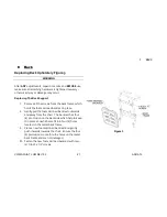
Page 21: ...holds the foam skinned backrest in place 2 Gently pull the foam skinned backrest outwards and away from the chair The backrest has four 4 protrusion on the backside which help to keep it in place and which also fit into four 4 holes located on the metal back frame 3 Place a new foam skinned backrest and gently push inwards towards the chair Ensure the four 4 protrusions come thru the holes on the ...

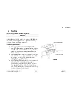
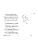
Page 22: ... locking clips from the commode frame tubing such that the seat assembly becomes independent from the commode 2 Gently grasp the new seat pad assembly from the sides and line up the approximate location of the seat locking clips with their respective frame tubing that they will lock onto 3 Push the seat assembly down onto the frame and ensure that the commode seat opening is oriented in the manner...

Page 23: ... wheel or caster locks are engaged before removing potty Also ensure that the wheelchair is in the zero or normal position such that the seat angle is about 3 3 Gently grasp the handle of the potty and slide the potty out from the wire potty holder in a direction away from the commode 4 Place the lid on the potty as shown below and ensure the lid and potty properly assemble together The potty lid ...

Page 24: ...Installing Potty 1 Turn the commode around so that one can see the back of the commode and potty 2 Ensure the wheel or caster locks are engaged before installing potty Also ensure that the wheelchair is in the zero or normal position such that the seat angle is about 3 3 Remove the lid on the potty if any and ensure that the potty is properly sanitized 4 Gently grasp the handle of the potty and sl...

Page 25: ...cated in each wheel The mechanism allows the casters to be independently locked in place so that the commode does not move In most instances one has to only the front two casters for the attendant propelled version and use the rear wheel locks on the self propelled version Adjusting Commode Seat Height 1 Remove the two snap clips located on the lower frame front side 2 Adjust the position of the c...

Page 26: ...of the caster assembly to the same position as the front casters and hold the casters in place 6 Place the snap clips back into the lower frame back side to secure the caster assembly to the frame Ensure the hole used by the snap clip is at the same position on both sides such that the frame is straight and not at an angle Note When the height of the commode is changed one must ensure that the com...

Page 27: ...ull on the trigger The chair should tilt from 3 to 33 3 The attendant can release the trigger handle at any time while the chair is tilting in order to place the occupant at a desired position angle 4 In order to return the commode to normal or zero position the attendant should grasp the stroller trigger handle and pull on the trigger while pulling the handles up The commode should return to the ...

Page 28: ...le below to achieve the desired seat to floor height The Front Caster and Rear Caster Should be set to the same height 2 Ensure that no weight is on the commode while performing the operations 3 Ensure after changing the seat to floor height that the commode is still operational and that no wheel flutter or instability occurs Figure 9 COMMODE TYPE STF FRONT INCHES CASTER HOLE STF REAR INCHES ATTEN...

Page 29: ...o remain in the main tube by sliding 4 Tighten the plunger knob to secure the anti tipper to the main frame assembly Removing the Anti Tippers 1 Loosen the plunger knob 2 Remove the anti tipper tube by sliding it out of the main frame tube 3 Screw back the plunger into the main frame assembly so that it would not get lost Adjusting the Anti Tippers 1 Loosen the plunger knob on the side frame of th...

Page 30: ...ity for repairs 3 Contact Future Mobility directly by telephone fax or e mail to obtain information regarding repair at Future Mobility facilities 4 You will be asked by the Customer Service Representative for the serial number that is affixed to the wheelchair 5 If any of the following conditions are observed the wheelchair must be serviced at Future Mobility a Any part of the frame is cracked or...

Page 31: ...onth b Protect the paint with a coat of non abrasive auto wax every three months 3 Axles and Pivot Joints a Clean around axles and moving parts WEEKLY with a slightly damp not wet cloth b Wipe off or blow away any dust or dirt on axles or moving parts WARNING Do not use abrasive powders or scouring pads on painted surfaces Do not ever submerge chair in water Do not use cleaning products without co...

Page 32: ...sferred to a different person from the original owner FOR TWO 2 YEARS Wheelchair Back and Cushions Excluding Upholstery 1 Future Mobility Healthcare Inc guarantees the back and cushion to be free of defects in material and workmanship for two years Wheelchair Components Excluding Limitations 1 Future Mobility Healthcare Inc guarantees the wheelchair components to be free of defects in material and...

Page 33: ...ts parts 3 This warranty does not include any labor or shipping charges incurred in replacement part installation or repair of any product 4 For warranty service please contact the dealer from whom you purchased your FMHI product In the event you do not receive satisfactory warranty service please write directly to FMHI 5 DO NOT return products to FMHI without our prior consent The defective unit ...

Page 34: ...____________________________________ City Country Postal Code ________________________________________________ Telephone _______________________________ Purchased Date _______________________________ Purchased From Dealer Name Address _________________________________ Product Purchased _________________________________________________ Serial Number ___________________________________________ Print...

Page 35: ......

Reviews: