background image

850 REV04 REV DATE: 09/03/2014                                                                                                                                                         

Page 

9

 of 

16


4.0 Prism Back Installation Instructions


7. 

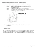
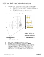
To install the longer mounting pins, please refer to the instructions bellow


• 

Remove the back from the wheelchair and secure in place.


• 

Using wrench, loosen the inside nut and replace standard pins to


the longer pins


• 

Carefully tighten nuts to secure the pins in place.


Ensure the pins do not rotate when tightening nuts.


Standard Mounting Pin


1/2” Longer Mounting Pin


Standard Mounting 

1” Longer Mounting Pin


Pins


Prism Back Front View 


8. 

Check that the fit and alignment of the back is correct


9. 

Fully tighten the Cane Clamp Screws on each side of the back


10. 

Once the back is properly secured to the back canes, the user can be


seated in the wheelchair in order to establish the optimal depth and 
recline settings for the back. With the user in the chair, loosen the 
Depth/Recline Adjustment Screws, position the back at the desired 
depth and recline angle, and re-tighten the screws to lock in place.


Summary of Contents for Prism BASIC

Page 1: ...850 REV04 REV DATE 09 03 2014 Page 1 of 16 PRISM BACKS BASIC ULTRA TRUEFITT AIR BACK AND SUPER BACK FOR KIDS 850 REV04 REV DATE 09 03 2014...

Page 2: ...equired Page 4 5 3 0 Before Installation Page 5 9 4 0 Prism Universal Hardware Installation Instructions Page 10 5 0 Disengaging the Prism Back Page 11 6 0 Head Neck Support Attachment Page 12 7 0 Tru...

Page 3: ...Cane Clamps 4 Cane Inserts 6 Depth Recline Adjustment Screws 6 Cane Clamp Screws 2 Backing Plate 2 0 Tools Required Wrench 1 2 Allen Key 3 16 Tape Measure Ruler Mounting pins on the chair back Adjusta...

Page 4: ...sition see Fig 1 below By altering the orientation of the Cane Clamps with the Back mounting Plates the hardware can be positioned to provide a rear most mounting position for the back if desired see...

Page 5: ...lamp Screws 3 per clamp in order to open the clamp enough to fit around the back posts Install clamps inserts if required 3 Starting on one side position the Cane Clamp at the desire height on the bac...

Page 6: ...tions Warning DO NOT install this equipment without first reading and understanding this instruction booklet If you are unable to understand these instructions contact a healthcare professional dealer...

Page 7: ...lower adjustment slots are provided on the Prism Hardware Back Mounting Plates to allow alternate mounting heights when back post obstacles are encountered Using the Alternate Mounting Slots will inc...

Page 8: ...sed position Step 3 With the upper pins in place snap lower pins into the latch mechanism at the bottom of the back mounting plates 6 In order to install the longer Mounting Pins first remove the oute...

Page 9: ...htening nuts Standard Mounting Pin 1 2 Longer Mounting Pin Standard Mounting 1 Longer Mounting Pin Pins Prism Back Front View 8 Check that the fit and alignment of the back is correct 9 Fully tighten...

Page 10: ...downwards on the left mounting plate until the ball plunger engages the latch open position 2 Push the release lever on the right mounting plate 3 Lower mounting pins will automatically ejected from t...

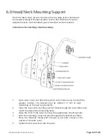
Page 11: ...ver and determine which set of holes to use to attach the adaptor bracket The Bracket may be shifted 1 5 left or right depending on the user requirements 2 Close the cover and carefully punch 2 holes...

Page 12: ...at the space next to the cube to be cut or carved 5 Trim each cube to the desired length using a sharp knife or scissors foam cutting saw works best 6 Reinstall trimmed foam blocks onto the aluminium...

Page 13: ...all connections remain secure Cover USE mild detergent and machine wash cold using gentle cycle DO NOT USE fabric softeners or bleach DO NOT machine dry air dry in shady area PLEASE NOTE The cover is...

Page 14: ...thout our prior consent The defective unit or parts must be returned for warranty inspection within thirty 30 days of the return authorization date Future Mobility Healthcare Inc will issue a return a...

Page 15: ..._ Street Address _________________________________________________ City Country Postal Code ________________________________________ Telephone _______________________________ Purchased Date __________...

Page 16: ...850 REV04 REV DATE 09 03 2014 Page 16 of 16...

Reviews: