background image

8


REAR WHEEL ADJUSTMENTS 

QSF: 390 – UM 1024404 REV03 08/20/13 

19 

Stellato 

Rear Wheel Adjustments 


 WARNING   

 
After 

ANY

 adjustments, repair or service and 

BEFORE

 use, 

make sure all attaching hardware is tightened securely – 
otherwise injury or damage may occur. 


WARNING  


If changing the size of the rear wheel or a change in the 
seat-to-floor height is desired, this procedure 

MUST

 be 

performed by a qualified technician. 
 

QUICK-RELEASE AXLES 


1.


Push in the detent pin of the quick-release axle 
(with wheel) and pull the axle out through the 
opening in the center of the rear wheel and axle 
spacer. 

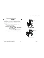
2.


Push in the detent pin of the quick-release axle  


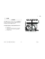
Figure 9: Rear Wheel Installation 


QUICK-RELEASE AXLE

REAR WHEEL

AXLE SPACER

 AXLE MOUNTING

PLATE-front position

REAR AXLE 

THREADED 

BUSHING

WHEELCHAIR

FRAME

 AXLE MOUNTING

PLATE-back position

Summary of Contents for Stellato

Page 1: ...510 REV03 REV DATE 08 20 2013 USER MANUAL...

Page 2: ...ooting 9 Labels 10 2 Front Riggings 11 Installing 11 Removing 12 3 Foot Plate Height Adjustment 13 4 Elevating Leg Rest Operation 14 5 Arms 15 6 Flip up Arm Rests 16 7 Replacing Upholstery 17 REPLACIN...

Page 3: ...S AND FORKS 22 Adjusting Front Caster Angle 23 11 Anti Tippers 24 Installing Adjusting The Anti Tippers 24 Installing Anti Tippers 25 ADJUSTING THE ANTI TIPPERS 26 12 Wheel Locks Operation 27 ADJUSTIN...

Page 4: ...er instructions WARNING DO NOT install this equipment without first reading and understanding this instruction booklet If you are unable to understand these instructions contact a healthcare professio...

Page 5: ...wheels always test the stability of the chair before use Never stand on the footplates during transfers in and out of the wheelchair Ensure wheel locks are fully engaged while stopped on any incline...

Page 6: ...21 o ARM STYLES Full length adjustable T Style or Flip back FRONT RIGGINGS Pin Style swing away dual swing away elevating headrests WEIGHT CAPACITY 250lbs 114kg PRODUCT WEIGHT 31 lbs OVERALL DIMENSION...

Page 7: ...ERAL Wheelchair rolls straight no excessive drag or pull to one side FRAME AND CROSSBRACES Inspect for loose or missing hardware Inspect for bent frame or cross braces WHEEL LOCKS Do not interfere wit...

Page 8: ...binding when lifted and spun Inspect for cracked bent or broken spokes HANDRIMS Inspect for signs of rough edges or peeling FRONT CASTERS FORKS Inspect axle assembly for proper tension by spinning cas...

Page 9: ...lem with the wheel chair Chair Veers Right Left Chair Wheels Sluggish Turn or Performance Caster Flutter Squeaks and Rattles Looseness in Chair Solutions Check tires for correct and equal pressure Che...

Page 10: ...o Labels Stellato Labels can be found on the lower frame underneath the seating bed of the wheel chair WARNING Do not operate without anti tippers mechanism in place Unit may tip backwards WEIGHT CAPA...

Page 11: ...ging assembly to the side open front rigging is perpendicular to wheelchair 2 Install the hinge plates on the front rigging assembly onto the hinge pins on the wheelchair frame 3 Push the front riggin...

Page 12: ...024404 REV03 08 20 13 12 Stellato Removing 1 Pull the front rigging release lever outward Rotate swingaway front rigging assembly outward 2 Lift the swingaway front rigging assembly off the hinge pins...

Page 13: ...nt riggings and swingaway elevating legrest 1 Remove the front rigging assembly Refer to INSTALLING REMOVING THE FRONT RIGGING in this section of the manual 2 Remove footrest bracket bolt Slide footre...

Page 14: ...ng Leg rest 1 To adjust the angle of the elevating leg rest turn the handle knob counter clockwise to disengage from the index rod 2 Lift the leg rest to the desired angle 3 Re tighten the handle knob...

Page 15: ...rvice and BEFORE use make sure all attaching hardware is tightened securely otherwise injury or damage may occur Arm Height Adjustment Height Adjustable Arm Rest 1 Loosen knob 2 Lift armrest until des...

Page 16: ...e sure all attaching hardware is tightened securely otherwise injury or damage may occur Arm Height Adjustment Height Adjustable Arm Rest 4 Loosen knob 5 Lift armrest until desired position is acquire...

Page 17: ...hardware is tightened securely otherwise injury or damage may occur REPLACING THE SEAT UPHOLSTERY 1 Remove the front universal plugs that retain the existing insert rod to the wheelchair seat rail 2...

Page 18: ...back upholstery 3 Pull the existing back upholstery up and over the mounted back cane 4 Install the NEW back upholstery over the mounted back cane 5 Slide the loose back cane through the NEW back upho...

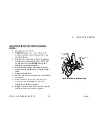
Page 19: ...in the seat to floor height is desired this procedure MUST be performed by a qualified technician QUICK RELEASE AXLES 1 Push in the detent pin of the quick release axle with wheel and pull the axle o...

Page 20: ...ly released BEFORE operating the wheelchair The locking pins MUST be protruding past the inside of the rear wheel axle bushing for a positive lock Keep locking pins clean Future Mobility Healthcare In...

Page 21: ...elchair by grasping the armrest of the wheelchair closest to you 3 Tilt the wheelchair towards you raising the opposite wheel and caster off the ground floor 4 Push downward on the TOP of the seat rai...

Page 22: ...This procedure can be performed if replacing the exact same size front caster 1 Remove dust cover 2 Remove the locknut that secures the fork to the caster headtube 3 Drop the front caster and fork ou...

Page 23: ...n a straight downward position d Adjust locknuts according to freedom of caster swing 8 Test wheelchair for maneuverability 9 Readjust locknuts if necessary and repeat STEPS 7 to 8 until correct 10 Sn...

Page 24: ...eights Refer to the chart in this section of the manual for correct usage and adjustment If these requirements CANNOT be achieved DO NOT us the wheelchair Contact a qualified technician If changing th...

Page 25: ...engaged and release buttons fully protruding out of adjustment holes Ensure both anti tippers are adjusted to the same mounting hole Installing Anti Tippers Press the release buttons IN and insert th...

Page 26: ...nd floor MUST be maintained at all times ADJUSTING THE ANTI TIPPERS 1 Press the release buttons on the wheeled portion of the anti tipper and slide it up or down to achieve the 1 to 2 clearance 2 Chec...

Page 27: ...ry or damage may occur 1 Ensure the wheelchair is not moving before engaging the wheel locks 2 Perform one 1 of the following a Push to Lock to engage push the wheel lock handle forward b Pull to Lock...

Page 28: ...ic tires and HOLDS the occupied wheelchair in place when pushed 4 Securely tighten the bolt and locknut or socket screws securing the wheel lock to the wheelchair frame 5 Engage the wheel lock 6 Measu...

Page 29: ...deterioration and if found contact a qualified technician DO NOT attempt to move the wheelchair by hand grips if they are broken DO NOT sit or transfer into the wheelchair unless it is fully open and...

Page 30: ...d out of the wheelchair every precaution should be taken to reduce the gap distance Turn both casters parallel to the object you are transferring onto When transferring to and from the wheelchair ALWA...

Page 31: ...elchairs as a weight training apparatus Future Mobility Healthcare Inc wheelchairs have NOT been designed or tested as a seat for any kind of weight training If occupant uses said wheelchair as a weig...

Page 32: ...e and indicate the nature of the defect DO NOT return products to FMHI without our prior consent The defective unit or parts must be returned for warranty inspection within thirty 30 days of the retur...

Page 33: ......

Page 34: ......

Page 35: ......

Page 36: ......

Reviews: