SuperPro Series Installation Manual
9. Then reinstall each RJ45 keystone jack into the blue bezel. Place bottom of jack into bezel
and then snap in the top of the jack into place.
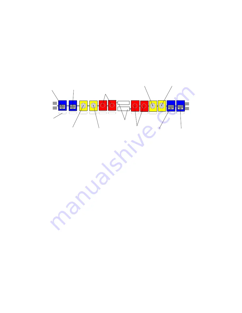
See Zone Diagram in Figure 4 below.
Yellow Cat5
cable (Data)
Blue Cat5
cable
(Phone)
Pink RG6 coax
cable (Down steam
to panel)
Black RG6 coax
cable (Upsteam to
plate)
Future fiber optic
or extra cable
connections
Zone labels
Future fiber optic
or extra cable
connections
Yellow Cat5
cable (Data)
Blue Cat5
cable
(Phone)
Zone Diagram
Port labels
Pink RG6 coax
cable (Down steam
to panel)
Black RG6 coax
cable (Upsteam to
plate)
Fig. 4
After you terminate every cable into the panel, you can then configure the front of the panel
(Figure 5):
1. Connect a 4 pair patch cable from the TP Hub to the zones where you want telephone signal.
2. Connect an RG-6 jumper from each used coaxial hub output to the coaxial cable downstream
side of each zone.
3. Connect an RG-6 jumper from each used upstream coaxial zone to the input side of the
coaxial hub.
4. Connect a CAT5e twisted pair jumper from any computer hubs to the appropriate zones.
5. Continue this procedure until all connections have been made.
Page 10
FutureSmart


