Section 40
00-02-0893
2014-07-18
-
11 -
Data Page
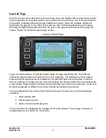
The Data Page shows a set of variables that are useful to know during operation. All of these
parameters are explained in the help pages accessed from the main menu.
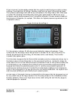
Figure 9.0 Data Page
In the example page shown in figure 9.0, the PIPs actually counted are 183, and PIPs that the
user entered into the program are 182. This difference will generate an alarm, but as long as
the PIP count tolerance is equal to or greater than 1, the system will continue to run. The CAM
Lead and Trail parameters are typical. The lead value is positive indicating it is in advance of
the 1/REV pulse, and the trailing edge is negative, indicating the trailing edge happened after
the 1/REV pulse. These are normal values. The CAM parameters are grayed out if the unit is
programmed to use one of the CAMLESS modes where no CAMREF signal is used.
CAMRef Pol indicates that the user-programmed polarity matches the measured value. The
CAMRef: High indicates the CAMREF signal was detected during the period it is marking a
logic high value, i. e. 10 volts. When the magnet passes under the sensor, the output will go to
a low voltage (< 1.0v), and this is a logic low level. The CAMREF input is sampled every few
degrees, and since during most of the revolution the target magnet is not under the sensor, a
display of “High” will be shown most of the time.
The remaining parameters are self-explanatory.

