background image

Air track 


4


-


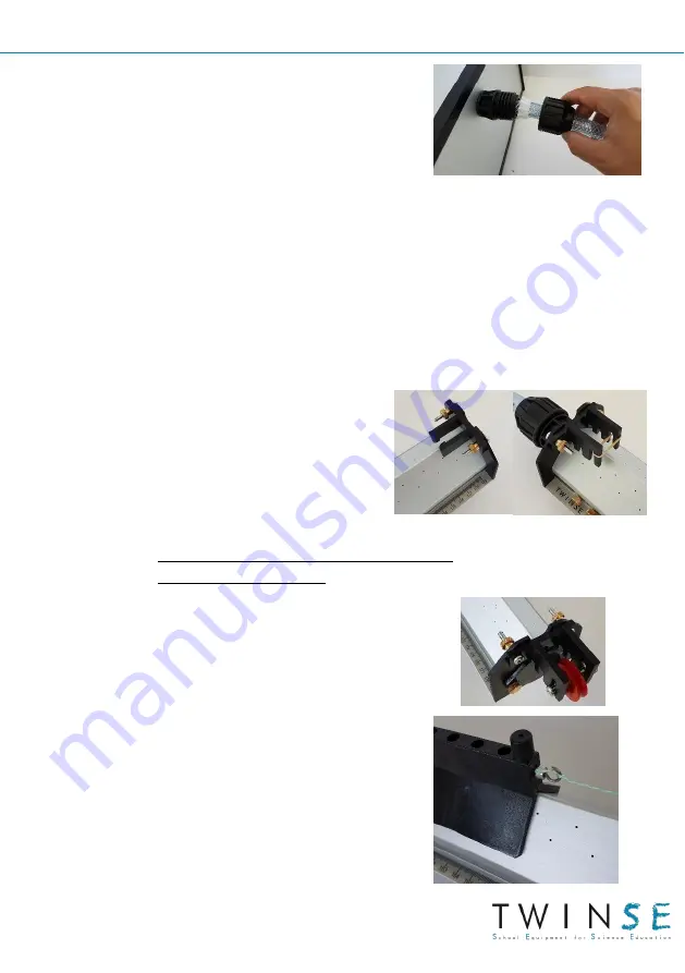
Take the air blower out of its packaging 
and  connect  the  hose  to  the  outlet  in 
exactly the same way.  


-


Connect the power lead to blower. 

WARNING:

 Check that the variator switch is on the lowest setting. 

Start the blower. 
 

-


Place  a  glider  on  the  track  and  increase  the  blower  power  until  it 
moves without any friction. 
Stop the glider and finely adjust the horizontality of the track so that 
the glider no longer moves. 
 

-


Fit the glider brake on the end (cover 
side). 
Fit the elastic launcher at the other 
end.  


2-


Setup for uniformly accelerated motion 
or as an inclined plane 


-


On  the  cover  end  replace  the  glider 
brake with the pulley holder. 


-


Fit the hook accessory onto the glider. 
Attach  the  thread  to  the  hook,  then 
attach the other end to a mass. 


Summary of Contents for DM241013

Page 1: ...INSTRUCTIONS FOR USE Air track DM241013 Track accessories DM241014 Air blower DM241016 Electromagnetic launcher...

Page 2: ...inelastic collisions 2x2 g 2 photogate brackets 2 barrier rods for photogates 0 8 g 1 pulley holder with thread for accelerometer 1 elastic launcher 1 brake 1 connection hose 1 spirit level DM241014 A...

Page 3: ...nderneath the track which has small holes all along its length cf diagram opposite Setting up and use 1 Basic setup Take the track out of the cardboard tube Fix the adjustable feet underneath the trac...

Page 4: ...blower power until it moves without any friction Stop the glider and finely adjust the horizontality of the track so that the glider no longer moves Fit the glider brake on the end cover side Fit the...

Page 5: ...ider OPERATION Place the launcher accessory against the launcher compressing the spring Press the button to hold the glider in position When you let go of the button the glider is released and propell...

Page 6: ...ckets Put the photogate barrier rods on the gliders Pass the glider under the photogate to check that it cuts through the beam without touching the sensor If it does not adjust the sensor height Conne...

Page 7: ...launch Place the photogates x mm apart and measure the glider s travel time between the 2 photogates Repeat the operation moving the 2 photogates further along the track keeping the x mm gap between t...

Page 8: ...m apart and measure the glider s travel time between the 2 photogates Repeat the operation 3 times moving the 2 photogates X mm further along the track keeping the x mm gap between them This demonstra...

Page 9: ...efore the impact This gives you the initial momentum 0 1 0 Measure the velocity of the first glider after the impact To do this place the photogates after the second glider from which barrier rod has...

Page 10: ...Air track 10 This demonstrates that the momentum is conserved 0 1 2 In addition as the kinetic energy is conserved 1 2 1 2 0 1 2 1 1 2 2 This gives 1 0 1 2 1 2 2 0 2 1 1 2...

Page 11: ...the track Measure the velocity of the first glider before the impact This gives you the initial momentum 0 1 0 Measure the velocity of the 2 glider assembly after the impact To do this place the phot...

Page 12: ...art and measure the glider s travel time between the 2 photogates Repeat the operation 3 times moving the 2 photogates X mm further along the track keeping the x mm gap between them This demonstrates...

Reviews: