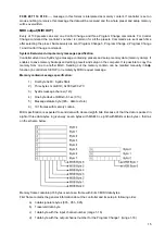
background image

Structure

1 -

O

N

/O

FF switch

10 – 13 SWITCH sec

tion buttons:

21 -

SAVE – store

2 – 9 AUXILIARY secti

on buttons:

10 -

SW 1 output switch or in 

Fun

 mode digit 9 of the numeric keyboard

22 -

shift but

ton

2 -

AUX 1 output switch or

11 -

SW 2 output switch or in 

Fun

 mode digit 0 of the numeric keyboard

23 -

ENTER – confirm

in 

Fun

 mode digit 1 of the numeric keyboard

12 -

SW 3 output switch

24 -

ESC – escape

3 -

AUX 2 output switch or

13 -

SW 4 output switch

25 -

LED display

in 

Fun

 mode digit 2 of the numeric keyboard

14 – 20 LOOP secti

on buttons:

26 -

DOWN dec

rease

4 -

AUX 3 output switch or

14 -

BUFFER – on/off buffe

r switch or

27 -

UP – increase

in 

Fun

 mode digit 3 of the numeric keyboard

in 

Fun

 mode MUTE – silent tuning switch

28 -

OUT – output signal connector

5 -

AUX 4 output switch or

15 -

LOOP 1 switch or

29 -

LOOP 1 to L

OOP 6 – effects’ connectors:

in 

Fun

 mode digit 4 of the numeric keyboard

in 

Fun

 mode MEM P

R

OT. –

 memory access lock switch

RETURN – effect loop input connector,

6 -

AUX 5 output switch or

16 -

LOOP 2 switch or in 

Fu

n

 mode SETUP switch

SEND –- effect loop output connector

in 

Fun

 mode digit 5 of the numeric keyboard

17 -

LOOP 3 switch or

30 -

IN – guitar signal input

7 -

AUX 6 output switch or

in 

Fun

 mode 

CTRL CHG –

 controller value switch

31 -

TUNER – guita

r tuner connector

in 

Fun

 mode digit 6 of the numeric keyboard

18 -

LOOP 4 switch or

32 -

SW1&2, SW3&4 – output connectors to 

control the amp

8 -

AUX 7 output switch or

in 

Fun

 mode P

R

CHG-1 – device 1 Program numbe

r switch

33 -

AUX 1 to AUX 4 – connectors

in 

Fun

 mode digit 7 of the numeric keyboard

19 -

LOOP 5 switch or

34 -

MIDI IN – MIDI input connector

9 -

AUX 8 output switch or

in 

Fun

 mode P

R

CHG-2 – device 2 Program numbe

r switch

35 -

MIDI OUT – MI

DI output or Soft THRU connector

in 

Fun

 mode digit 8 of the numeric keyboard

20 -

LOOP 6 switch or

36 -

12V DC – Power supply connector

in 

Fun

 mode P

R

CHG-3 – device 3 Program numbe

r switch

3

Summary of Contents for MIDI Guitar Controller

Page 1: ...Instrukcja obs ugi User Manual Bedienungsanleitung MGC 6 Guitar Controller Midi...

Page 2: ......

Page 3: ...mand ___________ 9 CC Controller s number programming ___________________________________ 10 MIDI OUTPUT mode programming_______________________________________ 10 Bulk memory dump ___________________...

Page 4: ...presets programming and copying To avoid accidental presets changing controller posses the six level memory protection Basic features true passive signal path true bypassed by electro mechanical rela...

Page 5: ...digit 4 of the numeric keyboard in Fun mode MEM PROT memory access lock switch RETURN effect loop input connector 6 AUX 5 output switch or 16 LOOP 2 switch or in Fun mode SETUP switch SEND effect loo...

Page 6: ...4 Diagram of devices connectable to the MGC 6...

Page 7: ...parasitic capacitance appearing when all the effects are switched off SEND outputs should be connected with IN effects inputs and RETURN inputs should be connected with OUTPUTs of particular effects...

Page 8: ...l of AUX output Lighting of the decimal point after the P letter means that actual preset was modified MIDI program numbers programming MGC 6 enables to control three MIDI devices separately on differ...

Page 9: ...e memory protection Preset s copying Controller enables to copy the whole preset The procedure is similar to preset s saving Selecting the preset No to copy as well as storing could be done by the use...

Page 10: ...m Change 3 channel number Co4 Control Change channel number Cno CC Controller s number nio MIDI output mode bdP Bulk memory dump rdP Memory dump permission CEE Clearing of the presets memory MIDI INPU...

Page 11: ...s The available range is from 1 to 16 Displaying of the r letter with the channel number means that the number of this channel is already reserved r for other Program Change command Example below show...

Page 12: ...ke controller s memory backup Sending and receiving System Exclusive dump memory message enables editing the presets and setups on the computer Sending the System Exclusive dump memory message is only...

Page 13: ...ction have to be done using mono or stereo Jack Jack cable Y type cable stereo Jack 2 x mono Jack or need dedicated cable or adapter offered by G LAB The actual list of available cables and adapters y...

Page 14: ...C by two effect loops Two stereo effects switch TRUE BYPASS AUX A B SWITCH connection AUX A B SWITCH enables switching two different signal sources to one OUTPUT Connection of the devices should be do...

Page 15: ...Program number Function 0 99 1 100 Preset number 100 101 mute ON Control Change Controller s number Controller s value Function 0 63 AUX1 switching off 20 64 127 AUX1 switching on 0 63 AUX2 switching...

Page 16: ...3 switching on 0 63 LOOP4 switching off 55 64 127 LOOP4 switching on 0 63 LOOP5 switching off 56 64 127 LOOP5 switching on 0 63 LOOP6 switching off 57 64 127 LOOP6 switching on 0 63 BUFFER switching o...

Page 17: ...py the memory from one to another MGC Sending out the memory contain can be recalled manually in bdp function in controller s SETUP or remotely by MIDI request message Memory contain message specifica...

Page 18: ...RY 8 b 1 byte with the information about the SWITCH OUTPUTs state according to the scheme below S1 S4 SWITCH 1 SWITCH 4 X reserved c 1 byte with the information about the LOOPs state according to the...

Page 19: ...ange 0 127 7 20 31 52 61 Prog Change 1 128 1 101 System Excl O O System Common Song Pos X X Song Sel X X Tune X X System real time Clock X X Commands X X Aux Messages Local ON OFF X X All Notes OFF X...

Page 20: ...18...

Page 21: ...vice into an outlet on a circuit different from that to which the receiver is connected Contact with the manufacturer see Before calling a service Consult the dealer for help Certificate of Conformity...

Page 22: ...ment Parties collecting such equipment organise a system including local collection points shops and other units allowing to return such equipment This Directive assures an user free of charge utilisa...

Page 23: ......

Page 24: ...d phone 48 32 272 20 21 fax 48 32 272 81 90 Web site www glab com pl Export Department phone 48 32 272 30 51 inter 34 48 32 272 20 21 inter 366 e mail rydygier elzab com pl Technical Support phone 48...

Reviews: