background image

5

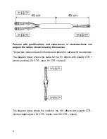
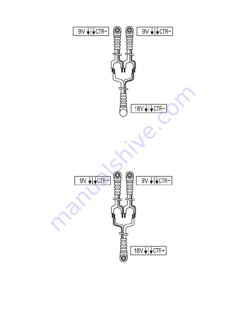
The diagram below shows the cable for supplying the effects requiring 18V

DC with polarity CTR + (centre positive) (two 9V CTR - inputs, 18V CTR +

output).

Summary of Contents for PB-1

Page 1: ......

Page 2: ......

Page 3: ...to 4 and 5 to 8 see the scheme Each of PB 1 outputs posses short circuit and thermal protection Outputs No 4 and 8 posses switches to change voltage polarity Thanks to applied in the PB 1 SMPS technology DC output voltage is guaranteed in the range from 100V to 240V line voltage there is high output power in proportion to small size and weight PB 1 doesn t possesses typical mains transformer which...

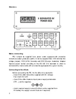
Page 4: ... to the IEC320 C14 standard to which is connected the mains cable with a connector appropriate for a given country Connecting to the effects Before connecting the PB 1 to the effect it is needed to check if the effect should be supplied with DC voltage If so check if it is 9V check if the effect features input power supply polarization CTR centre negative check required supply current if effect ca...

Page 5: ...apter to the effects which need to be supplied from alternating current AC It is recommended to cover the connectors of changed polarity cable with attached labels The diagrams below explain descriptions on those labels For the effects that require 12V DC voltage it is needed to use individually bought Adapter 2x9V 12V DC CTR neg 0 35A product code 00865 For the effects that require 15V DC voltage...

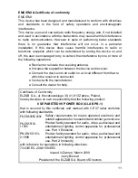
Page 6: ...The packet contains heat shrink tubes and labels for cables with descriptions The diagram below shows the cable for the 9V effects with polarity CTR centre positive 9V CTR input 9V CTR output The diagram below shows the cable for the 18V effects with polarity CTR centre negative two 9V CTR inputs one 18V CTR output ...

Page 7: ...5 The diagram below shows the cable for supplying the effects requiring 18V DC with polarity CTR centre positive two 9V CTR inputs 18V CTR output ...

Page 8: ...ame part of the path e g on the effects or before the amp input and are placed one by one in the signal path the effects aren t the overdrive boost type effects with high gain or the effects consume the current impulsively e g those equipped with LED display The diagram below shows the cable for supplying two 9V effects with polarity CTR centre negative from one 9V source 9V CTR input two 9V CTR o...

Page 9: ...7 Linking wires without soldering The diagram below shows the way of linking two wires The diagram below shows the way of linking three cables ...

Page 10: ...to use M4 screw adapter base posses bushings with M4 threads The adapter can be also fastened to the rack 19 systems by the use of 1U RMS Panel product code 00829 and M3 screws supplied with the adapter Technical parameters Dimensions width 108 mm Depth 130 mm Height 40 mm Weight 0 9 kg Power supply nominal 100V 230V ...

Page 11: ...9 ...

Page 12: ...10 ...

Page 13: ...eiver Connect the device into an outlet on a circuit different from that to which the receiver is connected Contact with the manufacturer Consult the dealer for help Certificate of Conformity ELZAB S A ul Kruczkowskiego 39 41 813 Zabrze Poland hereby declares on own responsibility that the following product 8 SEPARETED 9V POWER BOX G LAB PB 1 that is covered by this certificate and marked with CE ...

Page 14: ...rties collecting such equipment organise a system including local collection points shops and other units allowing to return such equipment This Directive assures an user free of charge utilisation of such delivered equipment This device is made of materials which can be recycled or utilised after becoming out of use Proper handling of wasted electric and electronic equipment reduce demand for row...

Page 15: ......

Page 16: ......

Reviews: