gm-elektronik.swiss | adm@gm-elektronik.swiss
USO
I
Le postazioni
FMD 2001
e
FMD 2012
sono dotate di una serie
di LED atti a segnalare gli stati operativi del sistema.
Di seguito vengono indicate nel dettaglio le corrispondenze
LED/stato.
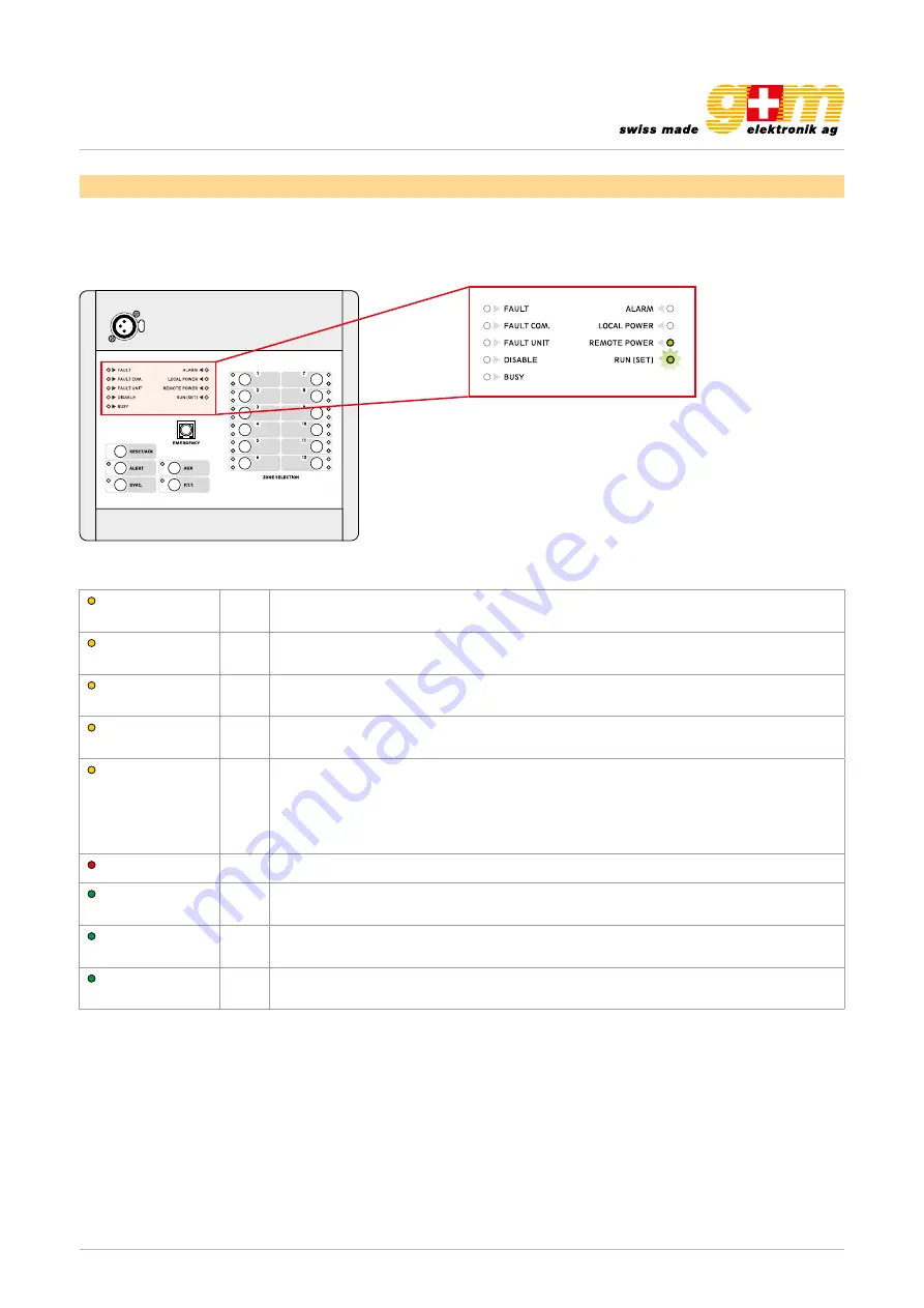
FAULT
Giallo
Indica uno “Stato di guasto” generico nel sistema.
Vedere menu FAULTS del VAIE 2250 per visualizzare gli elementi in guasto.
FAULT COM.
Giallo
Indica mancanza di comunicazione dati tra la postazione stessa e VAIE 2250.
Vedere menu FAULTS del VAIE 2250 per visualizzare gli elementi in guasto.
FAULT UNIT
Giallo
Indica un guasto generico alla postazione stessa.
Vedere menu FAULTS del VAIE 2250 per visualizzare gli elementi in guasto.
DISABLE
Giallo
Segnala uno “Stato di disabilitazione” attivo. Indica la presenza di almeno una zona
in cui non è previsto l’invio di messaggi d’emergenza.
BUSY
Giallo
Lampeggiante in stand-by: indica che un’altra postazione con priorità più bassa sta
occupando il sistema.
Lampeggiante: durante una chiamata broadcast, indica la durata del segnale di
preavviso.
Fisso: indica che un’altra postazione con priorità più alta sta occupando il sistema.
ALARM
Rosso
Indica lo “Stato di allarme” in corso nel sistema.
LOCAL POWER
Verde
Indica la presenza dell’alimentazione locale in corrente continua applicata alla presa
esterna della postazione.
REMOTE
POWER
Verde
Indica la presenza dell’alimentazione fornita dal VAIE 2250 tramite il cavo CAT5.
RUN/SET
Verde
Lampeggiante: indica che la postazione funziona correttamente, normale operatività.
Fisso: indica che è attiva la fase di configurazione della postazione (SET).
Possono essere identificate diverse tipologie di utilizzo:
• Invio di messaggi d’emergenza in vivavoce.
• Invio di messaggi d’evacuazione/allerta pre-registrati.
• Chiamate broadcast.
• Selezione zone (solo FMD 2012).
• Funzione AUX per richiamo messaggi preconfigurati.
• Reset dei messaggi d’emergenza.
• Silenziamento cicalino per riconoscimento guasto (ACK).
3.1 Attivazione dell’emergenza manuale
Per l’attivazione, premere il pulsante
EMERGENCY
, protetto da
sportellino: appena attivata l’emergenza, il sistema si pone nella
condizione di selezione generale delle zone.
Fig. 3.1.1
È possibile attivare l’emergenza solo se le condizioni di priorità assegnata lo consentono.
Nota:
per maggiori informazioni sugli stati operativi del sistema, consultare la Sezione
“Operatività e
nomenclatura” del manuale del
VAIE 2250
.
Datasheet 1811.001
DIGITAL MICROPHONE CONSOLE VA-FMC-512
Page 3 | 9
2. Operating instructions
The microphone station is equipped with a set of LED’s for signalling the operating states of the system:
FAULT
yellow This indicates a generic «failure status» within the system.
See the FAULTS menu of the VA-500
to identify the failed components.
FAULT COM.
yellow This indicates a lack of communication of data between the station in question and the
VA-500. See the FAULTS menu of the VA-500 to identify the failed.
FAULT UNIT
yellow This indicates a generic failure of the station in question. See the FAULTS menu of the
VA-500 to identify the failed components.
DISABLE
yellow This signals an active «disabled status». It indicates the presence of at least one zone to
which sending of emergency messages is not envisaged.
BUSY
yellow This LED flashes on stand-by: it indicates that another station with a lower priority is occu-
pying the system.
Flashing: during a broadcast call, it indicates the duration of the chime signal.
Steady ON: this indicates that another station with a higher priority is occupying
the system.
ALARM
Red
This indicates an «alarm status» existing within the system.
LOCAL POWER
green This indicates the presence of the local DC power supply applied to the external
socket of the station.
REMOTE POWER green This indicates the presence of the power supply provided by the VA-500 through the
CAT5 cable.
RUN / SET
green Flashing: this indicates that the station is working correctly and operating normally.
Steady: this indicates that the station configuration stages is active (SET).
N.B.: For further information about the operating states of the system, consult the «Operating conditions and Terminology»
section of the VA-500 operating instruction. Various different types of use can be identified:
• Sending of emergency messages in the live mode
• sending of pre-recorded evacuation/alert messages
• Broadcast calls
• Zone selection
• AUX function for calling up pre-configured messages
• Resetting of emergency messages