


gm-elektronik.swiss | adm@gm-elektronik.swiss
SETTINGS
UK
4.6 LOW-CUT filter
To set the LOW-CUT filter,
press the ALERT and EVAC keys simultaneously and hold them down for more
than 3 seconds
. When the
RUN/SET
LED stops flashing and remains steady ON, release the keys.
Press the RESET/ACK. key. The LEDs will indicate the current settings:
AUX
LED ON =
filter ON
P.T.T.
LED ON =
filter OFF
Holding the
RESET/ACK
key down, press
AUX
to activate the filter or
P.T.T.
to de-activate it.
To leave the settings mode and save the changes made, press the
ALERT
and
EVAC
keys again. The
RUN/SET
LED will start flashing again. If you do NOT want to save the changes made, simply wait for the timeout (about 10
seconds), after which the previous settings will be restored.
Note: To check the effects of the changes described under points 4.3 to 4.6 above, a normal call so as to
listen to your own voice is recommended.
Note for INSTALLERS:
While installing and configuring the system, it may be necessary to mute the failure signalling buzzer temporarily.
To do this, there is a switch (
11
) on the rear panel, which has to be positioned with a small screwdriver. Remember
to re-activate the buzzer after completing the operations.
4.5 Output level
To set the output level,
press the ALERT and EVAC keys simultaneously and hold them down for more than
3 seconds
. When the
RUN/SET
LED stops flashing and remains steady ON, release the keys. Holding the
ALERT
key down, press
AUX
to increase the output level or
P.T.T.
to decrease it.
The appropriate LEDs will flash to indicate that the adjustment is being made. Once the (minimum or maximum)
limits have been reached, the LEDs will remain steady ON. To leave the settings mode and save the changes made,
press the
ALERT
and
EVAC
keys again. If you do NOT want to save the changes made, simply wait for the timeout
(about 10 seconds), after which the previous settings will be restored.
DATI TECNICI
I
1
FMD 2001
FMD 2012
N° di zone selezionabili
-
12
Tensione d’alimentazione
24 V
CC
Assorbimento massimo @24V
CC
60 mA
130 mA
Livello d’uscita tipico
300 mV
Distorsione
< 1%
Rapporto segnale/disturbo
> 60 dB
Rapporto segnale/disturbo (pesato “A”)
> 65 dBA
Risposta in frequenza
130 ÷ 19.000 Hz
Filtro LOW CUT
-3 dB / 380 Hz
Dimensioni (L x H x P)
140 x 80 x 200 mm
230 x 80 x 200 mm
Peso netto
0,77 kg
1,55 kg
•
Nota
•
FBT declina ogni responsabilità per danni a cose e/o persone derivanti dall’uso non corretto dell’apparecchio o da
procedure non rispondenti a quanto riportato sul presente libretto.
Nel continuo intento di migliorare i propri prodotti, FBT si riserva il diritto di apportare modifiche ai disegni e alle
caratteristiche tecniche in qualsiasi momento e senza alcun preavviso.
Datasheet 1811.001
DIGITAL MICROPHONE CONSOLE VA-FMC-512
Page 9 | 9
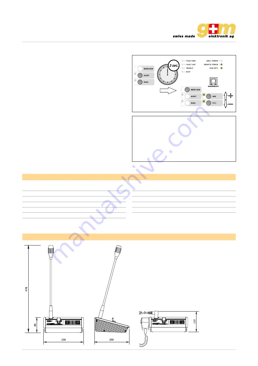
3.6. LOW-CUT filter
To set the LOW-CUT filter, press the ALERT and EVAC keys
simultaneously and hold them down for more than 3 se-
conds. When the RUN / SET LED stops flashing and remains
steady ON, release the keys.
Press the RESET / ACK. key. The LED’s will indicate the cur-
rent settings:
AUX LED ON = filter ON
P.T.T. LED ON = filter OFF
Holding the RESET / ACK key down, press AUX to activate
the filter or P.T.T. to de-activate it.
To leave the settings mode and save the changes made,
press the ALERT and EVAC keys again. The RUN / SET LED
will start flashing again. If you do NOT want to save the chan-
ges made, simply wait for the timeout (about 10 seconds),
after which the previous settings will be restored.
Note: To check the effects of the changes described under
points 4.3 to 4.6 above, a normal call so as to listen to your
own voice is recommended.
Note for INSTALLERS:
While installing and configuring the system, it may be ne-
cessary to mute the failure signalling buzzer temporarily.
To do this, there is a switch (11) on the rear panel, which
has to be positioned with a small screwdriver.
Remember to re-activate the buzzer after completing the
operations.
Number of selectable zones
12 zones
Power supply
24 VDC
Maximum absorption (24 VDC)
130 mA
Typical output level
300 mV
Distortion
<
1%
S / N ratio
> 60 dB
S/N ratio (weighted “A”)
> 65 dBA
Dimensions in mm
Technical data
Frequency response
130–19'000 Hz
Low-cut filter
-3 dB / 380 Hz
Dimensions (W × H × D)
230 × 80 × 200 mm
Weight
1.55 kg
Colour
Dark grey
Material
Plastic


