background image


Voltage of the oven:

 check  whether  voltage  of  the  equipment  is  the  same  of your

electric supply. 


Wall socket:

 socket where oven is to be connected should be a monophase or 3-phase

fix  plug,  dimensioned  for  the  nomina l current  of  the  protection  circuit ( thermal-electrical
breaker), allowing full exemption of plug pins, without any clearances, so that sharp live parts
cannot be touched by human hand. 


Socket wiring

: they should be rigorously in accordance with their respective compensations

as described  in  the  Brazilian Standard  NBR 5410 - ABNT ( Associação Brasileira de Normas
Técnicas -  the  Brazilian  Association  for  Technical  Standards ). Should you have any doubts
consult a specialized electrician. 

         Protection: 

: at the circuit where oven is to be plugged to, there must be a thermal-electrical


circuit breaker as per the table below. 


Ground wiring or Earth wire: 

ground wire of your oven should be connected to an effective

earth  cable, thus  preventing  from  personal  risks. Connection to a ground wire is necessary
under any voltage, and should not be connected to the neutral wire of the power supply, neither
to  the  hydraulic, gas  or  electrical  piping, nor  the  faucets, etc. For  a perfect  ground wiring,
observe instructions under the Brazilian Standard NBR 5410 - ABNT, “Grounding Wire”.

      Electrical extension cords or the like:

 for no reason whatsoever should you connect any

other equipment to the same wall socket. That can cause an overload on the electrical supply
and/or bad contact. Overloads can cause prejudicial heating to insulation of the connections,
the terminals or surroundings of the conductors, and cause damages and it may even burn the
installations or the product. 

      It is the customer's responsibility if it is not possible to turn equipment on.


   A CONNECTION TO A GROUND WIRING SYSTEM IS MANDATORY.

ELECTRIC SUPPLY

GAS TURBO OVEN

FTG 300-240-150-120

         
        Model

         
        Model

         
        Dimensions:


       FTG 120


       FTG 120


       FTG 150


       FTG 150


       FTG 240


       FTG 240


       FTG 300


       FTG 300


       1300


       1300


       1470


       1470


       580


       660


       1160


       1000

Mono 110V

Mono 220V

Mono 110V

Mono 220V

1/4 Hp

1/4 Hp

1 Hp

1 Hp

15A

15A

15A

15A


       1530


       1610


       1700


       1770


       820


       820


       860


       860


      980


      980


      940


      940

Width

including

Switchboard

( mm )

Voltage

Width not

including

Switchboard

( mm ) )

Motor Power 

Width

including

Base

( mm )

Protection Circuit

Breaker Recommended

Width not

including

Base

( mm )

Depth

( mm )

ATTENTION

 GROUNDING WIRE: Installing ground wiring is mandatory for safety matters whatever
voltage of the product. Be careful! Ground wiring should not be connected to neutral wire
of the power supply. neither to water nor gas pipes, etc.

           After  observing  recommendations described previously as for proper functioning of the
equipment, it will be ready to be used.  

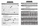
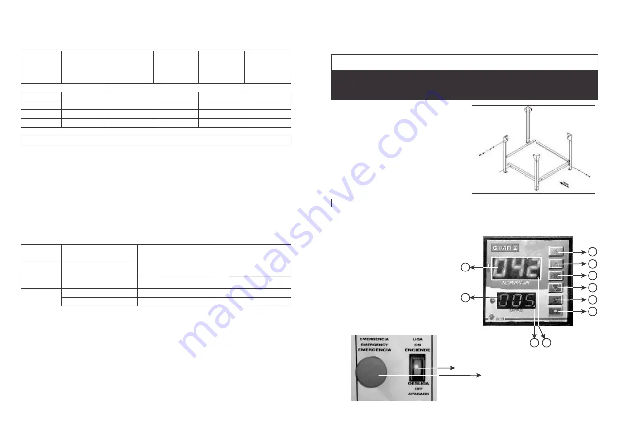
1)  Lamp Switch Key

2)  Timer Start Switch Key

3)  Decrease Switch Key ( - )

4)  (PGM) Programming

5)  Increase Switch Key (+)

6)  Steam Switch Key

7)  Time Display

8)  Temperature Display

9)  Flame Indicator

10) Indicator for Time Decreasing

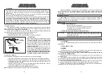
This supporting rack is supplied disassembled
only  for models FTG 120 - FTG 150. 
In  order  to  assemble it correctly, follow steps
shown in the drawing below:

HOW TO PUT YOUR EQUIPMENT INTO OPERATION

GAS TURBO OVEN

FTG 300-240-150-120

5) ASSEMBLING THE SUPPORTING RACK

6

1

8

7

10

On / Off Switch key

Emergency Switch Key

9

2

3

4

5

18

23

Summary of Contents for FTG Series

Page 1: ...o Ltda Rua adolfo Randazzo 2010 Bairro Vila Maestra Cx Postal 8012 CEP 95 034 970 Fone 0 XX 54 2101 3400 Fax 0 XX 54 2101 3408 Caxias do Sul RS Brasil 0 XX 54 2101 3400 FORNO TURBO G S HORNO TURBO G S...

Page 2: ...nical features 17 Producto dimensions electric supply 18 Installing hidraulic supply electric install 19 Installing Hidraulic install 22 Operation 23 Operation sequence to turn oven on 24 Operation co...

Page 3: ...min 10 min 12 min 15 min 0 5 0 5 1 0 1 0 1 27 1 27 1 52 1 90 1 0 1 0 1 2 1 5 5 Kpa 5 Kpa 5 Kpa 5 Kpa Press o de Trabalho Consumo GLP hora Kg Consumo GN 3 hora m Consumo Kw hora Tempo de Aquecimento Mo...

Page 4: ...s A conex o do fio terra necess ria em qualquer tens o n o devendo ser ligado ao fio neutro da rede torneiras tubula es hidr ulicas el tricas de g s etc Para um aterramento correto observe as instru e...

Page 5: ...OARD CLOSING 656 x 378mm 14 06394 TURBINE FLANGE ASSEMBLY 120 150 15 00396 MICRO SWITCH KEY TM 1307 18 06024 UPPER HINGE PLATE 124 5 x 50 mm 20 02275 SILICON TRIMMING FOR OVEN FLAME 23 00685 GAS OVEN...

Page 6: ...93 LH SUPPORT ASSEMBLY FOR CONVEYORS 08 06393 RH SUPPORT ASSEMBLY FOR CONVEYORS 09 06391 DOOR ASSEMBLY 10 06346 SWITCHBOARD 1194 x 171mm 11 06359 GAS SYSTEM PROTECTION PLATE 656 x 300mm 12 06568 SWITC...

Page 7: ...VALVE 33 02256 CONTACTOR CWM 9 01 220V 50Hz 60Hz 35 02687 CABLE PRESS 3 8 Pg9 36 02761 GAS OVEN HOSE ASSEMBLY FTG 37 06088 BURNER DUCT CLOSING 38 02635 NIPLE 5 8 UNF 39 06050 INJECTOR COUPLING PIPE 21...

Page 8: ...FTG 300 01 06096 INTERNAL CHAMBER ASSEMBLY 02 06049 LH EXTERNAL CLOSING 1218 x 1129 5mm 03 06048 RH EXTERNAL CLOSING 1233 x 1129 5mm 04 06047 REAR EXTERNAL CLOSING 1217 x 718mm 05 06057 UPPER EXTERNAL...

Page 9: ...SUPERIOR ANCHO BASE 67 06384 810 x 87mm PERFIL INFERIOR ANCHO TRABA BASE 68 ESTA PIEZA NO ACOMPA AA ESTE MODELO 73 02171 PHILIPS M6 x 16 INOX TORNILLO 74 00300 SEXT MA 06 x 16 TORNILLO 75 00306 FENDA...

Page 10: ...F 25 03914 LLAVE L D 29123 M4FT1EE3G UNIP 15A 26 02624 PORTA FUSIBLE 27 02634 UNI N 1 4 NPT X 1 4 NPT 28 02638 CODO 1 4 X 1 4 29 70176 V LVULA SOL 220V UX826C002 GAS 30 02620 V LVULA ESFERA 1 4 061109...

Page 11: ...NO GAS 24 01034 BOT N EMERG GIRAR PARA SOLTAR S NF 25 03914 LLAVE L D 29123 M4FT1EE3G UNIP 15A 26 02624 PORTA FUSIBLE 27 02634 UNI N 1 4 NPT X 1 4 NPT 28 02638 CODO 1 4 X 1 4 29 70176 V LVULA SOL 220V...

Page 12: ...ICO 1694 x 276mm 11 06059 CHAPA PROT SISTEMA GAS 750 x 300mm 12 06082 CIERRA PANEL CONTROL 1156 x 378mm 13 00661 LANA DE ROCA 14 06094 CONJ BRIDA TURBINA 15 00396 LLAVE MICRO INTERRUPTOR TM 1307 16 06...

Page 13: ...PAINEL CONTROLE 656 x 378mm 14 06394 CONJ TURBINA FTG 120 150 15 00396 CHAVE MICRO INTERRUPTOR TM 1307 18 06024 PLACA DOBRADI A SUP 124 5 x 50mm 20 02275 PERFIL SILICONE TIPO CHAMA FORNOS 23 00685 CO...

Page 14: ...ENTO EXT TRAS 700 x 678mm 05 06357 FECHAMENTO EXT SUP 962 5 x 845 5mm 06 06323 CONJ PROTE O H LICE 07 06393 CONJ SUPORTE ESTEIRAS ESQ 08 06393 CONJ SUPORTE ESTEIRAS DIR 09 06391 CONJ PORTA 10 06346 PA...

Page 15: ...2637 V VULA 5 KPA 32 02690 TRAFO ISOLA MONO 220W S12100VA12V6VA 33 02256 CONTACTORA CWM 9 01 220V 50Hz 60Hz 35 02687 PRENSA CABO 3 8 Pg9 36 02761 CONJ MANGUEIRAS FORNO GAS FTG 37 06088 FECHAMENTO DUTO...

Page 16: ...iales realizadas por la f brica 6 1 4 4 6 3 4 3 3 5 5 4 5 2 4 FUNCIONAMIENTO SECUENCIA PARA ENCENDER EL HORNO C DIGO DESCRI O DAS PE AS C DIGO DESCRI O DAS PE AS UTILITARIO REF FTG 300 01 06096 CONJ C...

Page 17: ...erificar si el horno est conectado a la red Verificar si hay energ a el ctrica en la red Para el buen funcionamiento y una larga vida til no utilice su horno en tempe ratura superior a los 250 C TEMPE...

Page 18: ...mpuestas por el fabricante When oven has reached the temperature desired proceed as follows 1 Open oven door At this moment micro switch key will automatically turn turbine off 2 Load batch and close...

Page 19: ...d After that press switch key again and the equipment will be back to regular control condition NOTE During programming if there is a pause longer than 3 seconds equipment will resume regular control...

Page 20: ...al heating to insulation of the connections the terminals or surroundings of the conductors and cause damages and it may even burn the installations or the product It is the customer s responsibility...

Page 21: ...ater to come in directly from outdoor water supply because of the pressure that can be generated Observe instructions carefully because too much water can damage the equipment and compromise useful li...

Page 22: ...80 83 19 20 21 21 22 23 24 25 26 27 28 29 30 31 FRENTE DETALHE 38 39 39 40 41 42 81 82 43 44 45 46 47 48 49 50 51 52 53 54 55 56 57 58 61 59 60 62 63 64 65 66 67 68 32 33 34 35 36 37 S acompanham os...

Reviews: