background image


Page. 37                                                                                                                                          

LM P RS485 Data Logger


T

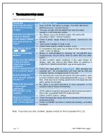
ROUBLESHOOTING GUIDE


Table 9 Troubleshooting guide 


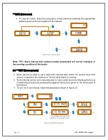
Note:  if you face any other problem, please contact G-Tek Corporation Pvt. Ltd.


PROBLEM 

CORRECTIVE ACTION 

How to get the status 
of the batch (running 
or not)? 
 

  Note the STR LED status on display. The STR LED will be 

blinking at every 1 second interval. 

  The user can also see the status from menu for batch 

operation, it will show stop option. 

How Alarm condition is 
shown on display?


  ALL (Alarm Low) or ALH (Alarm High) LED will be ON 

according to alarm high/low condition. 

If LED display is Blank, 
then what should be 
done? 


  Check  if  power  supply  adapter  is  properly  connected  to  the 

device. 

   Also check if adapter is faulty or not. 

  Check power supply polarity is proper or not. 

Why Display shows 

undr

” / “

over

”? 

  If the pressure input goes out of range of then display shows 

undr

” / “

over

” on display. 

How to acknowledge 
Buzzer? 

  Buzzer  is  acknowledged  by  pressing  UP  and  ENTER  keys 

simultaneously. Buzzer will be silent for Alarm OFF time delay 
(AOFT). 

How to give Zero Offset 
or how to remove 
offset value at zero 
condition? 

  At  zero  condition  (open  condition),  if  any  value  shows  on 

display,  user  can  remove  this  offset  value  by  pressing  a 
FUNCTION ,DOWN and ENTER keys at the same time. 

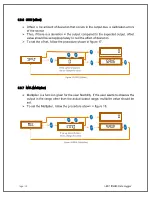
How to change the unit 
of the pressure input? 
 

  Follow  the  steps  given  i

section  6.3.5

.    After  selecting  the 

required  unit  ,  its  corresponding  unit  LED  will  be  ON  and 
pressure reading on display will be in that unit. 
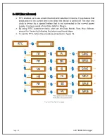
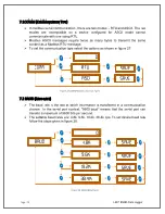
How to change the 
baud rate and  parity of 
the device?  
 

  For changing the baud rate and parity, the user needs to enter 

in communication menu using password(refer 

section 7

 ). Note 

that , if the batch is in running condition then the baud rate and 
parity cannot be changed. 

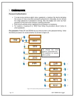
What is the procedure , 
if user forgets 
password? 

  No,  there  is  no  such  procedure  to  reset  password,  in  this 

situation contact factory immediately. 
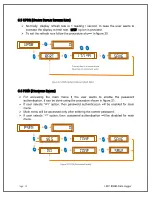
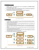
Why the RTC  is not 
updated? 

  If RTC battery is drained  and power is off for some time period, 

then it can be possible that RTC might not work. 

  Check the RTC battery  voltage. 

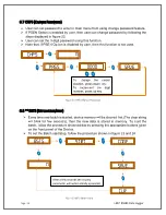
What to do if device 
does not communicate 
with  remote software? 

  Check the baud rate ,parity and device address of the device is 

selected properly. 

  Check the RS485 connection( twisted pair polarity ) and cable 

continuity .  

Summary of Contents for LM Pro 63 Series

Page 1: ......

Page 2: ...verall mechanical dimensions for Square plate data logger 10 Electrical installation 11 6 1 Wiring diagram for Data logger 11 6 2 RS485 connection Diagram 12 Operation 13 7 1 Front panel of Data logge...

Page 3: ...INT Store interval 27 Communication 28 7 1 COMM Communication Type 29 7 2 BAUD Baud rate 29 7 3 DADR Device address 30 7 4 PRTY Parity 30 7 5 AVGE Average Enable 31 Modbus RTU Communication 32 8 1 Mod...

Page 4: ...ure Units with their range 7 Table 3 Connection notations 11 Table 4 RS485 Connection notations 11 Table 5 Status of LED s 15 Table 6 Configurable item 17 Table 7 MEI Current pressure data query 34 Ta...

Page 5: ...gment LED display 16 Figure 10 Main menu sequence 18 Figure 11 Configurable parameters 19 Figure 12 AOND Alarm on delay 20 Figure 13 AOFT Alarm off delay 20 Figure 14 ALSH Alarm set point high 21 Figu...

Page 6: ...Using it beyond the specified limit can cause the damage to the product and personnel also Do not use the product if there are signs of damage to the housing Carry out only the maintenance and repair...

Page 7: ...etc are all settable through 4 keys Data is scanned every second It has RS485 2 4 wire communication port to connect to any SCADA using MODBUS RTU ASCII protocol User can get the current data and devi...

Page 8: ...0 to 500 pascal refer Table2 for other units range Pressure Accuracy 1 5 FSD Pressure Input port Quick Connect Disconnect port 3 mm tube ID Environmental conditions Temperature Operating 5 to 65 o C S...

Page 9: ...h operation and store interval are not provided Mechanical Dimensions and Mounting Housing Material ABS Plastic Mounting Orientation Mounting unit in vertical plane Size L x W x D mm 190 x 190 x 40 Pa...

Page 10: ...ot be operated and the local representative contacted for instructions Ensure that all accessories and documentation is removed from the box There are two variants of LM P RS 485 data logger refer ord...

Page 11: ...er 5 1 OVERALL MECHANICAL DIMENSIONS FOR ROUND PLATE DATA LOGGER Figure 3 Overall mechanical dimensions for Round plate data logger Model No 63xx Figure 2 Front and back view of Square plate LM P RS48...

Page 12: ...TE DATA LOGGER Figure 4 Overall mechanical dimensions for Square plate data logger Model No 64xx Overall Dimensions approx Round plate 63xx Square plate 64xx Dimensions L x W x D mm 40 D 190 x 190 x 4...

Page 13: ...ations Code Connector Name Pin Number of connectors 1 2 3 4 5 Communication RS485 RX RX TX TX GND Note All wiring diagram connection are same for both models Code Connector Name Pin Number of connecto...

Page 14: ...ECTION DIAGRAM Figure 6 4 Wire RS485 Wiring diagram Multiple LM P RS485 devices can be connected with 4 wire RS485 is shown in figure 6 User can refer figure 7 if 4 wire to 2 wire RS485 conversion is...

Page 15: ...t every one second The Display will show gtec message for few seconds and then reading of pressure input The default pressure is in pascal which is indicated by PA LED unit1 User can reconfigure the c...

Page 16: ...or go to the next parameter This key is used to decrement the digits or go back to the previous parameter This key is used to save the parameter values to enter a menu submenu 7 2 ZERO OFFSET User ca...

Page 17: ...ed ALL Alarm Low ALL LED display and unit LED will blink if the pressure reading goes below alarm set point low value In normal condition Pressure value above alarm set point low ALL LED will remain i...

Page 18: ...ED display has the precision of 3 digits after decimal point Note that the display range of pressure value are set by menu using proper pressure unit For example if the selected pressure unit is pasca...

Page 19: ...tion Parameter Alarm on delay Delay time after which the buzzer will be activated Alarm off delay Delay time after which the buzzer will be activated Set point High The upper limit of value after whic...

Page 20: ...ed using front panel Keyboard by entering the function key User can enter the configuration as per their requirement Figure 10 shows the main menu sequence Pressure at room temp open condition display...

Page 21: ...figure 11 by pressing appropriate key of device user can configure the parameters The parameters are discussed subsequently in detail Note To go to the next parameter To go back to the last parameter...

Page 22: ...panel of the Device 6 3 2 AOFT Alarm off delay The alarm will be acknowledged by pressing UP key and ENTER key at the same time The buzzer will be deactivated for specific Alarm OFF time delay Alarm O...

Page 23: ...t us whenever device reading goes lower than the set value The device will generate the alarm if the reading goes out range and that value should be set from 500 to 500 pascal To set the Alarm set poi...

Page 24: ...er we should set the unit for the pressure input by pressing appropriate key from the menu The procedure for selecting the unit is shown in figure 16 Figure 16 Unit Sequence mbar pa kpa unit psi Mh2o...

Page 25: ...ation To set the offset follow the procedure shown in figure 17 6 3 7 MUL Multiplier Multiplier is a function given for the user flexibility If the user wants to observe the output in the range other...

Page 26: ...battery that is not connected to the normal power supply It serves needs of real time data for Device By using RTC parameter menu user can set Date Month Year Hour Minute second for Device by followi...

Page 27: ...wants to enable the password authentication it can be done using the procedure shown in figure 21 If user selects Yes option then password authentication will be enabled for main menu Main menu will...

Page 28: ...ime new batch is started device memory will be cleared first The clear string will blink for few seconds then the new data is stored in memory To start the batch follow the procedure shown below by pr...

Page 29: ...fixed time interval after which the current data from sensor is stored to the memory of Device while batch is running Store interval can be set in seconds and minutes combination by following the bel...

Page 30: ...g and show pressure reading parameter Each time to access menu password authentication is necessary For example if password is 0040 then follow the procedure shown below to enter password For password...

Page 31: ...set the communication type select the options as shown in figure 27 7 2 BAUD BAUD RATE The baud rate is the rate at which information is transferred in a communication channel In the serial port cont...

Page 32: ...are same parity bits in the communication devices then the devices will communicate with each other E g If the pressure device has parity bit odd then it can only communicate with the device having o...

Page 33: ...ch the display reading will not be stable To get the more stable reading averaging of pressure input data is required Averaging of pressure input data can be enabled disabled by selecting YES NO optio...

Page 34: ...cks each character and the entire message frame during receipt When devices communicate on a MODBUS serial line using the RTU Remote Terminal Unit mode each 8 bit byte in a message contains two 4 bit...

Page 35: ...ead only and read write locations Register Address High Register Address Low 0x10Write Preset Multiple Registers Set the content of read write locations Register Address High Register Address Low When...

Page 36: ...sure data request is as below Field Name Value hex Description Device Address 0x60 Value between 0x01 to 0xF7 1 t o247 Function code 0x03 Read holding registers Byte Count 0x04 Number of bytes Data Re...

Page 37: ...re device dependent The standard and extended device information of LM P RS485 data logger can be read by query request using Modbus function code 0x2B 0x0E hex which is shown in following example Que...

Page 38: ...hex Query Request Query Response MEI Standard 60 2B 0E 01 00 602B0E0100 CDBF 602B0E0101000003001 1472D54656B20436F72 706F726174696F6E0107 363331322D323002065 630312E30307B2A2746 4B3DEF0D MEI Extended...

Page 39: ...o Offset or how to remove offset value at zero condition At zero condition open condition if any value shows on display user can remove this offset value by pressing a FUNCTION DOWN and ENTER keys at...

Page 40: ...e Pressure Range Communication Type Software Type Memory Type 6 6X Pro 0 Universal Input 0 No Pressure 0 None 2 None 0 No Memory 1 Temperature 1 5mbar 1 RS 232 4 Gtek net Non Secure 1 Memory 2 Humidit...

Reviews: