46
10.2017 | 20734ES | Designed in Germany
EN
Motor-driven shoot-bolt lock for narrow stile systems
Installation instructions
B-1893x | B-1993x
y
y
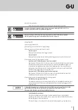
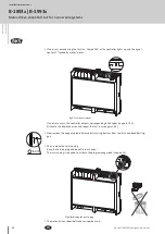
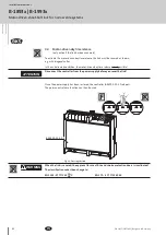
Connect the connection cable B 5940 0300 to the controller B-54900-01-3-9 (see point 2.4) as
indicated by the imprinted colour coding. In doing so, open the terminal clamps up to the lock-in
position and fully insert the cable ends (approx. 10 mm).
y
y
A connection is automatically established when closing the connecting terminals.
To take the cable back out, open the connecting terminals beyond the lock-in point. Lever the
cable carefully, e.g. using a precision screwdriver, out of the insulation piercing connecting device.
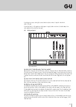
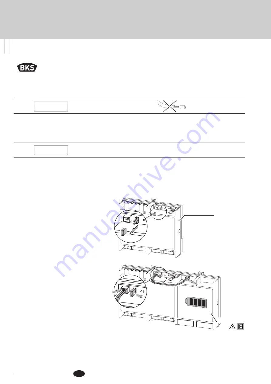
The controller B-54900-01-3-9 is delivered with the jumper inserted. If the controller is operated
without the emergency power backup system B-54903-23-3-9, remove it.
To connect the emergency power backup system B-54903-23-3-9, fully insert the 2-pin connection
cable into the controller and emergency power backup system and make sure the jumper is
inserted.
Do not strip the insulation off the cable ends!
NOTE
Cut off the damaged part of the cable before reinserting it into a terminal clamp!
NOTE
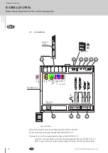
Fig.4: Connection of emergency power backup system
B-54900-01-3-9
B-54903-23-3-9
Summary of Contents for BKS B-1893 Series
Page 31: ...31 ...
Page 131: ...131 ...
Page 133: ...133 1 2 3 4 ...
Page 135: ...135 A 3 Profilfräsung A 3 Profile cutout A 3 Fraisage du profilé A 3 Fresado del perfil ...
Page 136: ...136 B 1893x B 1993x 10 2017 20734ES Designed in Germany Notizen Notes Notes Notas ...
Page 137: ...137 Notizen Notes Notes Notas ...
Page 138: ...138 B 1893x B 1993x 10 2017 20734ES Designed in Germany ...
Page 139: ...139 ...


