Installation, operating and maintenance instructions
Radio locks PRIME OFFICE 2170 (EN 179) for toughened glass doors
8
0-45648-3E-0-GB, modif. 1, sheet 8/20, Mod. No. G24578, www.g-u.com 01/2011
4
Assembly
4.1
General assembly instructions for emergency exit devices according to EN 179
An emergency exit device complying with this European standard always consists of:
Lock
(active- and / or passive leaf lock)
Fittings
(active- and / or passive leaf fitting)
Accessories
(fixing material, square spindle, vertical rods, switch lock)
Locking counterpart
(frame, strike plate, passive leaf lock, floor sockets)
A door closer and a profile cylinder are not always required. However, if used, they must be approved for use with the particular exit device
(see CE conformity certificate).
Only emergency exit devices using components listed in the CE conformity certificate may be used to EN 179. This also applies to the
supplementary installation of spare parts.
Due to different frame designs it may be impossible for the manufacturer to supply an appropriate strike. In this case the fabricator takes over
responsibility, in agreement with the manufacturer, to design and install an equivalent solution as demanded. See also approved strike plate
design
(Fig. 4
).
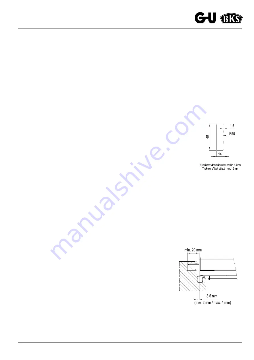
Before installing the emergency exit device, the door must be checked if it is properly installed and
not warped. Moreover, it is necessary to verify if the glass-to-frame and glass-to-glass distances
correspond to the dimensions given in these instructions.
Deadbolt and rods of the lock must engage in strike plates and floor socket without any friction at any time,
even if preloaded. Additionally it must be ensured that the retracted locking elements do not protrude as far as
to obstruct the movement of the door.
The emergency exit device must be operable smoothly and easily.
Stiffness may be sign of inappropriate assembly or distortion.
If door gaskets are used, ensure they do not affect the proper functioning of the exit device.
If emergency exit devices shall be fitted to glass doors, it is important that the glass quality is
toughened safety glass.
Fig. 4:
Strike plate design
to EN 179
PRIME OFFICE Series 21 locks are suitable for emergency exit devices on 1-leaf escape doors only. (Recess for latch)
They are not suited for use on double action swing doors and on fire or smoke protection doors.
The emergency exit device must be mounted according to these Assembly, Operation and Maintenance Instructions.
Especially the directions concerning attachment are to be followed carefully. The installer should pass the instructions on to the operator.
Operators of such exit devices must be instructed about use as intended.
As a rule, the operating means is installed between 900 and 1100 mm (approx. 1050 mm as a standard) above finished floor level. The
distance should be measured when door leaf is closed. If most of the users are small children, a lower installation height should be
considered.
For emergency exit devices with lever handles, especially in the case of door leaves with graded surface levels, it is important to avoid
possible risks of injury such as, e.g., the danger of trapping fingers or clothes.
To hold the door shut, no other components than those approved to EN 179 should be
installed. This does not exclude the installation of door closers. When using a door closer,
it must be ensured that children or the elderly are not hindered from operating the door.
While following the assembly instructions, it is particularly important to ensure that all
strikes and covers are completely installed and attached.
On the inside (in escape direction), a clearly visible sign indicating "use handle to open" or
a corresponding pictograph should be attached either on the fittings themselves - if there
is sufficient space - or immediately above the fittings. The minimum size of the pictograph
(white colour on green background) should be 8000 mm². It is possible to use the
pictograph to EN 179, image A.1.
The arrow should point towards the handle (installed condition).
Dimensional requirements for proper installation see
Fig. 5
.
Fig. 5:
Dimensional requirements

