Installation, operating and maintenance instructions
Radio locks PRIME OFFICE 2170 (EN 179) for toughened glass doors
11
0-45648-3E-0-GB, modif. 1, sheet 11/20, Mod. No. G24578, www.g-u.com 01/2011
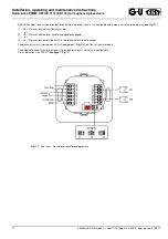
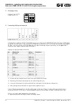
Relay R2 enables the emission of one of three different electrical signals. It is configured with jumpers set in the following way (
see Fig. 11
):
J1: R2 = Status of locking cam (factory setting)
or
J2: R2 = Status of outside lever handle (engaged/disengaged)
or
J3: R3 = Status of lock battery (battery OK / low-battery alarm level reached)
The particular status is indicated on LED L2 (
see page 7, Fig. 3
) at the front of the wall module.
The output of latchbolt monitoring signals is provided by relay R1 which is not configurable.
Status indication is on LED L7 (
see page 7, Fig. 3
).
Fig. 11:
Rear view / wall module connection diagramme

