46
Multi-point locks electrically couplable or with monitoring contacts
Installation instructions
SECURY 19 EK | 19 EK EVP | 19 S | 19 S EVP
04.2016 | G31347 | Designed in Germany
DE
EN
FR
ES
Supplied connecting cable (from multi-point lock to junction box):
Art. no. B 5490 0300, Length 10 m (Type LiYY 14 x 0.14 mm²)
Cable cross section
(for customer-provided cable
from junction box)
Length
up to
Cross section
10 m
0.5 mm²
40 m
0.75 mm²
50 m
1.0 mm²
75 m
1.5 mm²
125 m
2.5 mm²
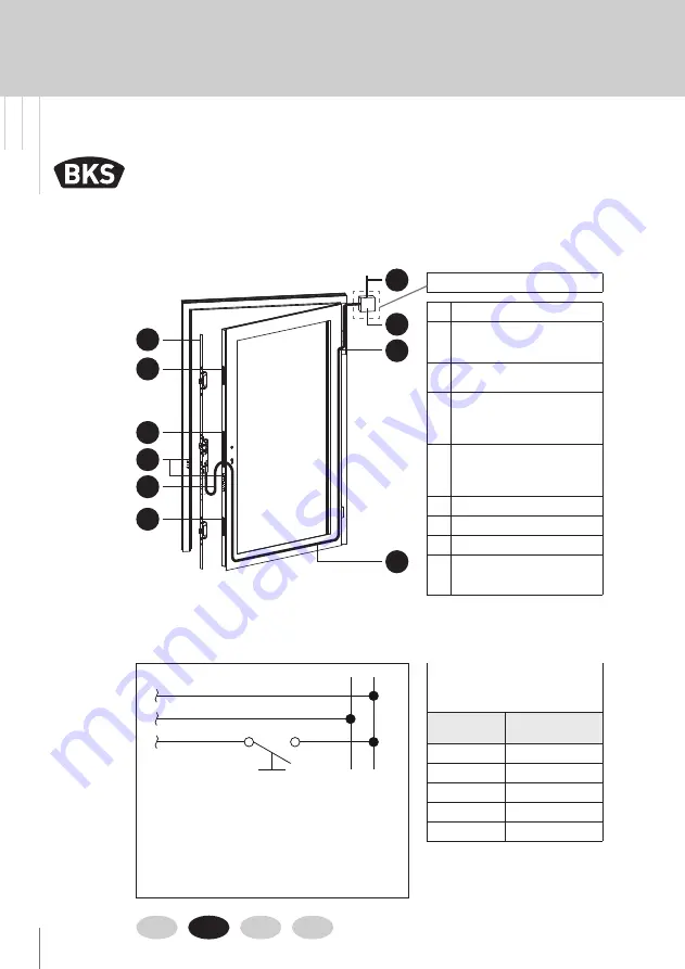
1
Supply line
2
Junction box
(connection see wiring
diagram)
3
Cable duct
or SECURE
connect
4
Cable path
(Install connecting cable
in glazing bead. Drill hole
below lock case recess.)
5
1-leaf: SECURY 1970 /
1970 EVP / 1975 /
1916 S / 1916 S EVP
2-leaf: SECURY 1971 / 1919 S
6
Latchbolt pocket
7
Lock pocket
8
Cable loop
9
Escape door strike and
latchbolt pocket EVP
(only 1970 EVP / 1916 S EVP)
see wiring diagram below
Installation of SECURY 1970 / 1970 EVP / 1971 / 1975 / 1916 S / 1916 S EVP / 1919 S
Installation conditions
3.3
Electrical
installation
Wiring diagram SECURY 1970 / 1970 EVP / 1971 / 1975
(
–
)
(
+
)
Brown (plus)
External
control contact
e.g.:
intercom
door opener button
access control
time switch, etc.
External
operating
voltage
12-24 V DC,
stabilised
White (minus)
Pink (control signal)
1
5
6
6
7
8
9
2
3
4
Summary of Contents for Secury 19 EK
Page 115: ...115 ...


