50
Multi-point locks electrically couplable or with monitoring contacts
Installation instructions
SECURY 19 EK | 19 EK EVP | 19 S | 19 S EVP
04.2016 | G31347 | Designed in Germany
DE
EN
FR
ES
±3°
0°
25°
6°
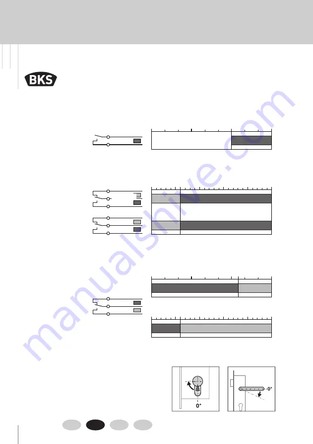
3.4.2 Switching points SECURY 1916 S / 1916 S EVP / 1919 S
Monitoring contact
for cylinder cam
Description of contacting related to cylinder cam position 0°!
0° = Lever handle not actuated
* Lock case cover = label side of the lock case
Description of contacting related to cylinder cam position 0°!
0° = Lever handle not actuated
Latchbolt contact
Lever handle contact
lock case cover *
Lever handle contact
lock case bottom
The wiring diagrams for the switching points of the contacts are
shown in the basic position; i.e.:
Latchbolt projected
Lever handle
not
actuated (lever handle position 0°)
Cylinder in the key removal position (cylinder cam
not
actuated)
The contacts of the multi-point locks switch within the areas
highlighted in grey.
Rot
Gelb
60°±3°
0°
90°
65°±4°
0°
90°
0°
25°
6°
+10°
−4°
Grau
Grün
Blau
Graurosa
Weißgrün
Schwarz
Rotblau
Violett
Braungrün
Contacting of latchbolt contact (only SECURY 19 EK / SECURY 19 EK EVP for 1-leaf doors **)
through profile cylinder
through follower
** The 2-leaf door version does not have a latchbolt
contact. The latchbolt cannot be queried through
the shoot-bolt lock B-1990X-XX-X-X FSK (
F
allen-
riegel
s
chalt
k
ontakt - latchbolt contact).
Contacting of monitoring contact for
cylinder cam through profile cylinder
Contacting of lever handle contact
through follower
Red
Yellow
Grey
Blue
Green
Purple
Brown-green
Red-blue
Black
Grey-pink
White-green
Summary of Contents for Secury 19 EK
Page 115: ...115 ...


