background image


Installation 

and


Operating Manual 


BDA-PS7W/PS8NEPS-37/37-90-N 
BDA-PS7/PS8-37/37-90-N 

700/800 MHz Band Bi-Directional Amplifier  


Summary of Contents for BDA-PS7/PS8-37/37-90-N

Page 1: ...Installation and Operating Manual BDA PS7W PS8NEPS 37 37 90 N BDA PS7 PS8 37 37 90 N 700 800 MHz Band Bi Directional Amplifier ...

Page 2: ...INDUSTRY CANADA 4 ELECTRICAL SPECIFICATIONS 6 MECHANICAL SPECIFICATIONS 6 ENVIRONMENTAL CONDITIONS 6 MECHANICAL OUTLINE 8 CONNECTIONS 9 AVAILABLE OPTIONAL FEATURES 10 ALARM CONDITIONS 11 VARIABLE GAIN ADJUSTMENT AND LED INDICATORS 12 INSTALLATION 13 OPERATION 14 DIAGNOSTICS GUIDE 15 ANTENNA SEPERATION 15 APPENDIX 1 16 APPENDIX 1 17 APPENDIX 2 18 ...

Page 3: ...ment shouldn t be used if this protection is impaired The supplied power cord must be used along with an uninterrupted external power source HAZARDOUS LINE AND RF VOLTAGES This symbol is marked on the equipment where dangerous voltages are present Use extreme caution Both RF input and output connectors should be terminated prior to the application of the external AC source Otherwise contact with t...

Page 4: ...t by an attenuator at the output of the device RF EXPOSURE WARNING FCC The ERP limit as defined by the FCC is 37 dBm In order to comply with the FCC RF exposure requirements the antenna installation must comply with the following An antenna with 8 5 dBi gain must be installed so as to provide a minimum separation distance of at least 81 9 cm 32 3 inches between the antenna connected to the RF boos...

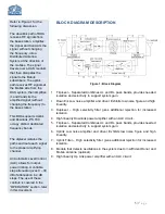
Page 5: ...attenuator gives 0 30 dB of attenuation in 2 dB steps The use of these controls is covered in the OPERATION section later in this document BLOCK DIAGRAM DESCRIPTION Figure 1 Block Diagram 1 Triplexer Separates Combines UL and DL pass bands provides needed isolation and selectivity to support system gain 2 Downlink Low noise amplifier and driver Exhibits low noise figure and high linearity 3 Duplex...

Page 6: ...ICAL SPECIFICATIONS May vary per unit see spec for more accurate information Size 14 1 x9 2 x16 RF Connectors N Type Female Weight 46 6 lb ENVIRONMENTAL CONDITIONS The unit is designed for indoor applications Operating temperature 20 C to 55 C Storage temperature 40 C to 85 C Composite Output Power 25 dBm 27 dBm 33 dBm 37 dBm Gain Flatness dB 1 5 2 0 1 5 1 5 Noise Figure dB 5 0 Max 4 5 Typ 5 0 Max...

Page 7: ...Output Composite Power Typical DC Current Draw 24VDC A Battery Back Up Time Hours Recommend Battery Rated Capacity 20 Hour Rate Amp Hours 37 dBm 3 55 4 17 75 8 35 5 12 53 25 24 106 5 33 dBm 2 47 4 12 35 8 24 7 12 37 05 24 74 1 31 dBm 2 35 4 11 75 8 23 5 12 35 25 24 70 5 27 dBm 2 1 4 10 5 8 21 12 31 5 24 63 Note We do not guarantee specifications under Battery Back Up power ...

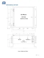
Page 8: ...8 P a g e MECHANICAL OUTLINE Figure 3 Mechanical Outline ...

Page 9: ...ctions must be made through cables with characteristic impedance of 50 ohms The BDA AC power is accepted through a standard 3 wire male plug IEC 320 with phase neutral and ground leads The AC power is wired to a high efficiency DC switching power supply which is CE and UL approved The power supply runs the amplifiers and the LED indicators The metal enclosure of the BDA is connected to ground Addi...

Page 10: ...nto a building s alarm system Dry contact will provide alarms for ALC and amplifier failure Local Alarming via dry contact 26 Pin Connector 026 A 26 Pin dry contact will be provided to hard wire into a building s alarm system Dry contact will provide alarms for ALC amplifier failure donor antenna failure and DC backup failure See details in appendix 1 Oscillation Detector and Shutdown ODSC ODSCRM7...

Page 11: ...n individual from accidentally pulling AC cord from unit as well as providing additional protection against direct water ALARM CONDITIONS The alarm monitors the current of both the uplink and downlink amplifiers An alarm condition will occur if either the uplink or downlink amplifiers are over or under its current tolerance Additionally each failure alarm indicator from the available features may ...

Page 12: ...uminates when the UL amplifier fails External DC LED optional Illuminates when the BDA is operating from a DC source Oscillation detection LED optional Illuminates when oscillation is detected Donor antenna alarm LED optional Illuminates when Donor Antenna is disconnected Mobile antenna alarm LED optional Illuminates when the mobile port is disconnected DL Manual Gain Attenuator Is a switch used f...

Page 13: ...s than the BDA gain will give rise to oscillations which will saturate the amplifiers and possibly cause damage to the BDA 3 Connect the cable from the donor antenna to the BDA connector labeled BASE and the cable from the service antennas to the BDA connector labeled MOBILE 4 See main Panel of the BDA and verify that both of the Uplink and Downlink attenuation is set to 30 dB via dial Attenuator ...

Page 14: ...nction is located in each power amplifier A red LED indicator located inside the BDA enclosure see figure 5 illuminates when output power meets or exceeds the ALC preset point To establish proper operating gain on the Uplink and Downlink paths begin with the Downlink Observe the red LED indicator labeled DL ALC Units are shipped from the factory with maximum attenuation 30 dB Decrease attenuation ...

Page 15: ...een those antennas is 15db above the system gain The amount of isolation that can be achieved between antennas depends on several factors such as the physical vertical and horizontal separation distance between the antennas polarization radiation pattern of the antennas the medium between the antennas antenna gain etc Antenna isolation can most accurately be determined through on site measurements...

Page 16: ...nnect G Way s special Donor Short Simulator Please note if you intend to use other components i e Lightning Protector between the base port and donor antenna make sure they have an open short N Type Female Female Donor Short Simulator N Type Male Female Donor Short Simulator Figure 7b Conditions for DC Backup Alarm The alarm monitors the AC power If the AC power fails and DC is connected the DC Al...

Page 17: ...17 P a g e APPENDIX 1 O26 Alarm Block Diagram ...

Page 18: ...etween horizontally separated transmitter and receiver antennas dh m the horizontal distance from the centre of interferer antenna to that of the interfered with receiver antenna dv m the vertical distance from the interferer antenna to the interfered with receiver antenna measured from radiation center to radiation center f Hz the wavelength of the interfered with system frequency band GTx dBi ga...

Reviews: