5
B
B
A
C
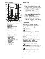
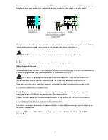
4.5 CLEARANCES
The clearances around the boiler as shown above must be
observed for correct operation.
A minimum of 200mm clearance must be maintained
underneath the boiler to allow replacement of the heating
elements if required. A minimum of 500 mm clearance must
be maintained in front of the boiler to enable easy access for
servicing.
Ensure sufficient space to make all water connections including
the outlet pipes for the heating safety valve which should be
routed to a suitable discharge point.
A: 50 mm
B: 10 mm
C: 200 mm
4.6 MOUNTING BRACKET
Mark the hole positions using the wall bracket as a template
per the diagram.
Fit bracket securely onto wall before lifting appliance into
position. Drill the holes and fit the bracket ensuring it is
level using suitable high strength screws, with appropriate
plugs or fixings, minimum M10 size.
Always use assistance if required. Wear suitable cut resistant
gloves when handling the appliance. Ensure safe lifting
techniques are used. Do not lift the appliance by attached
pipe-work or components. When lifting the boiler ensure
that the fixing elements and the wall have a sufficient load-
bearing capacity. Check the quality of the wall.
4.7 WATER CONNECTIONS
CAUTION: The hydraulic connections must be carried out respecting the flow and return marked on the
boiler.
CAUTION: When tightening or loosening threaded connections, always use suitable tools as open-end
spanners. Do not use pipe wrenches, extensions or unsuitable tools that may cause damage or water leaks.
Install purges in the radiators and high points of the installation.
Heating Flow & Return
These connections are ¾ “ for connection to 22mm pipe. Service valves should be installed at this position to
allow the boiler to be isolated for maintenance without the need to drain the entire system. The valves should be
of sufficiently large bore so not to restrict the heating circulation.
Single pipe heating systems are not recommended only a twin-pipe heating system should be used.
i


