4
All components for sealed system central heating are
built-in.
A suitable filling loop should be fitted
externally to comply with water supply
regulations (not supplied).
Heating and hot water functions will operate
independently but not simultaneously, with priority
always to hot water production unless this function is
not selected.
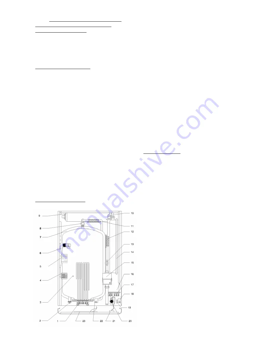
3.2 PRINCIPLE COMPONENTS
•
Insulated steel boiler unit with immersed
stainless steel elements INCOLOY800.
•
50 L stainless steel domestic hot water
store with CFC free insulation and
immersed stainless steel elements
INCOLOY800.
•
Fully integrated electronic control boards
featuring temperature control and
modulation function, pump over-run,
anti-seize and frost protection. Self-
diagnostic fault information.
•
Sealed system heating components:
circulating pump, 6L expansion vessel,
auto air-vent, 3 bar relief valve, pressure
gauge, water flow switch and
temperature limit safety thermostat.
•
Unvented hot water components: 7 bar
relief valve, 3L expansion vessel, non-
return valve and temperature limit safety
thermostat.
•
Silent TRIAC power switches.
•
Digital control board.
3.3 KEY TO COMPONENTS
1 DHW resistance.
2 Drain valve.
3 Temperature sensor location.
4 Connection block.
5 Main contactor.
6 DHW 7 bar relief valve.
7 Insulated tank 50L.
8 Anti-electrolysis DHW hose.
9 DHW expansion vessel 3L.
10 Automatic purge.
11 DHW power electronic PCB
12 Heating power electronic PCB
13 Heating flow detector.
14 Heating expansion vessel 6L.
15 Circulation pump.
16 Insulated heating header tank.
17 Heating resistance.
18 Heating safety thermal limit switch.
19 ON / OFF switch.
20 Heating 3 bar relief valve.
21 Pressure gauge.
22 DHW safety thermal limit switch.
23 Main electronic PCB.
3.4 SAFETY DEVICES
Safe operation under various conditions is ensured by
the following controls fitted inside the boiler:
o
Water flow switch that monitors water flow
in the heating system and will prevent
operation in case of a blockage, if the system
flow rate is below the permitted level, error
E3 will appear. Installation of a system by-pass
may be necessary (see 7.3 HEATING
SYSTEM FLOW SWITCH – E3 ERROR &
SYSTEM BY-PASS REQUIREMENTS).
o
Hot water high limit safety thermostat will
prevent operation if the temperature exceeds
80ºC. It requires re-setting manually.
o
Heating system high limit safety thermostat
will prevent operation if the temperature
exceeds 100ºC. It requires re-setting
manually.
o
Hot water pressure relief valve will discharge
to relieve excess pressure at 7 bar. (Requires
piping to a safe external discharge point.)
o
Heating system pressure relief valve will
discharge to relieve excess pressure at 3 bar.
(Requires piping to a safe external discharge
point.)


