


Technical Information
SYSTEM TROUBLESHOOTING
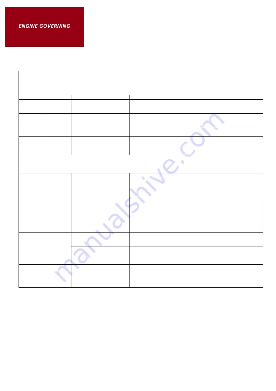
SYSTEM INOPERATIVE
If the engine governing system does not function, the fault may be determined by performaning the voltage tests described in Steps 1, 2,
3 and 4. [+] and [-] refer to meter polarity. Should normal values be indicated as a result of following the troubleshooting steps, the fault
may be with actuator or the wiring to the actuator. See the actual publication for testing details
Steps
Terminals
Normal Reading
Probable Cause of Abnormal Reading
1
F(+) & E(-)
Battery Supply Voltage
12 or 24 VDC
1.
DC battery power not connected. Check for blown fuse.
2.
Low battery voltage.
3.
Wiring error.
2
C & D
1.0 VAC RMS min., while
cranking.
1.
Gap between speed sensor and gear teeth too great. Check gap.
2.
Improper or defective wiring to the speed sensor. Resistance
between Terminals C & D should be should be 30 to 1200 fl.
3
P(+) & G(-)
10 VDC, Internal Supply.
1.
Short on Terminal P. (This will cause a defective unit.)
2.
Defective Speed Control.
4
F(+) & A(-)
1.0 - 2.0 VDC while cranking.
1.
Speed Adjustment set too low.
2.
Short/open in actuator wiring.
3.
Defective speed control.
4.
Defective actuator. See Actuator Troubleshooting.
UNSATISFACTORY PERFORMANCE
If the engine governing system functions poorly, preform the following test.
Symptom
Test
Probable Fault
1.
Do not crank. Apply DC
power to the governor
system.
1.
Actuator goes to full fuel. Then, disconnect speed sensor at
Terminals C & D. If the actuator is still at full fuel - the speed
control is defective. If the actuator is still at minimum fuel fuel
position - erroneous speed signal. Check speed sensor data.
Engine overspeeds.
2.
Manually hold the engine
at the desired running
speed. Measure the DC
voltage between
Terminals A (-) & F(+)
on the speed control
unit.
1.
If the voltage speed reading is 1.0 to 2.0 VDC; a.)
SPEED
adjustment is set above desired speed. b.) Defective speed control
unit.
2.
If the voltage reading is above 2.0 VDC; a.) Actuator or linkage
binding.
3.
If the voltage reading is below 1.0 VDC; a.) Defective speed control
unit.
4.
Gain set too low.
1.
Measure the voltage at
battery while cranking.
1.
If the voltage is less than 7VDC for a 12VDC system or less than
14VDC for a 24VDC system, replace the battery if it is weak or
undersized.
Actuator does not
energize fully.
2.
Momentarily connect
Terminal A & F. The
actuator should move to
full throttle position.
1.
Actuator or battery wiring in error.
2.
Actuator or linkage bringing.
3.
Defective actuator. See actuator troubleshooting.
4.
Fuse opens. Check for short in actuator or actuator wiring harness.
Engine remains below
desired governed speed.
1.
Measure the actuator
output. Terminal A & B,
while running under
governor control.
1.
If voltage measurement is within approx. 2 volts of the battery
supply voltage, then fuel control restricted from reaching full fuel
position. Possible due to interference from the mechanical governor,
carburettor spring or linkage alignment.
2.
Speed setting too low.
Insufficient Magnetic Speed Signal
A strong magnetic speed sensor signal will eliminate the possibility of missed or extra pulses. The
speed control unit will govern well with 0.5 volts RMS speed sensor signal. A speed sensor signal
of 3 volts RMS or greater at governed speed is recommended. Measurement of the signal is made
at
Terminals C
and
D.
The amplitude of the speed sensor signal can be raised by reducing the gap between the speed
sensor tip and the engine ring gear. The gap should not be any smaller than 0.020 in (0.45 mm).
When the engine is stopped, back the speed sensor out by 3/4 turn after touching the ring gear
tooth to achieve a satisfactory air gap.


