


Technical Information
To maintain engine stability at the minimum speed setting, a small amount of droop can be added
turn the
DROOP
adjustment
CW.
At the maximum speed setting the governor performance will be
near isochronous, regardless of the droop adjustment setting.
Contact for assistance if difficulty is experienced in obtaining the desired variable speed
governing performance.
Diagram 1.
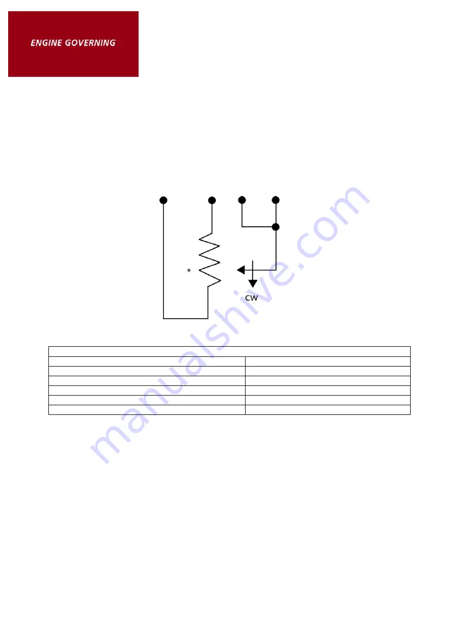
Table 4.
Variable Speed Range
Speed Range
Potentiometer
900 Hz
1K
2,400 Hz
5K
3,000 Hz
10K
3,500 Hz
25K
3,700 Hz
50K
*Select Proper Potentiometer Value from
Table 4.
SPECIFICATIONS
PERFORMANCE
Isochronous Operation/Steady State Stability ............................................... ±0.25% or better
Speed Range/Governor ....................................................................... 1K-7.5K Hz continuous
Speed Drift with Temperature ........................................................................ ±1% Maximum
Idle Adjust CW ..........................................................................................60% of set speed
Idle Adjust CCW ..................................................................................... Less than 1200 Hz.
Crank Termination Adjustment Range ................................................................300-2200 Hz.
Droop Range ........................................................................................... 1 - 5% regulation*
Droop Adj. Max. (K-L Jumpered) .......................................400 Hz., ± 75 Hz. per 1.0 A change
Droop Adj. Min. (K-L Jumpered) ........................................... 15 Hz., ± 6 Hz. per 1.0 A change
Speed Trim Range ............................................................................................... ± 200 Hz.
Remote Variable Speed Range ............................................... 500 - 7.5 Hz. or any part thereof
Speed Switch Adjustment Range .................................................................. 1000-10000 Hz.


